Description
Product Overview
CS-TX3-3.81X2.54-64TW is unusual among industrial spare parts because the number explains itself. Read as a construction descriptor rather than a catalogue entry, CS-TX3 is a board-family prefix, 3.81 is the pitch of the front pluggable terminal blocks in millimetres, 2.54 is the pitch of the back plane header, 64 is the number of ways, and TW says each way is a two-wire circuit. That is a complete mechanical specification in one string — and, for anyone used to reading OEM part numbers, that completeness is the warning rather than the reassurance. Real Alstom numbers in this cabinet do not behave that way: the control board beside it is CMP1838, ordered as TRVCO62345000 against drawing CP00005202; the I/O board is MC1AB37 against 4022.437.1856. Those are opaque, allocated numbers. This one is a description that someone turned into a part number.
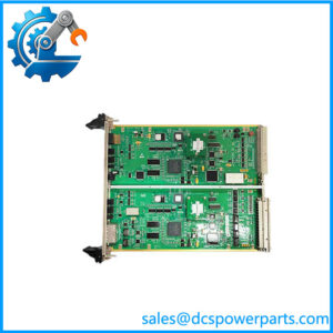
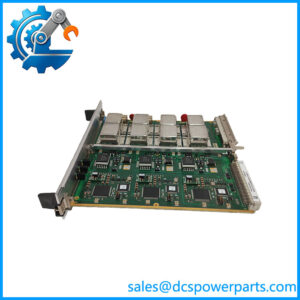
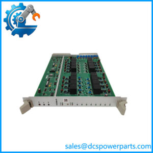
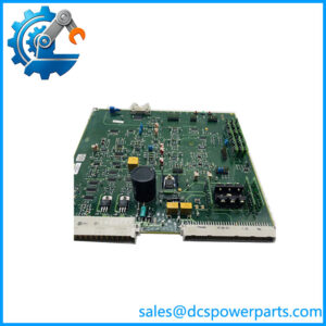
What the board does is nonetheless real and unglamorous. It is a marshalling board: 64 field circuits arrive at front pluggable terminal blocks, cross a passive PCB, and leave through a 64-way back connector that plugs directly into an I/O board. In an ALSPA P320 cabinet it sits between the field wiring and the acquisition electronics — the CMP1838 control board on one side of the rack, the STO1726KO1 or MC1AB37 I/O board on the other — and its entire contribution is to convert loose, individually landed field wires into one connectorised bundle. Nothing is amplified, isolated or converted; the board adds order, not function.
That role is why these boards matter disproportionately in an ageing plant. A marshalling board is the cheapest item in the cabinet and the one most likely to be damaged during any intervention: a fitter leaning on a terminal strip, a wrong wire landed during a loop check, a screwdriver across two adjacent ways. It is also the item whose failure produces the most confusing symptoms, because a fault on a passive board looks exactly like a field device fault, a card fault or a wiring fault. Having the right replacement, with the correct channel mapping, resolves a class of problem that otherwise consumes days of loop checking.
The commercial reality is the part that needs stating plainly. This designation appears in the market attached to a single supplier’s page, with no second source, no original photograph, no Alstom drawing and no GE document. The same supplier, describing the same cabinet, also publishes a decoding that does not hold together — it renders the string with stray spaces and a decimal point in the wrong place, reads the 2.54 segment as an “81-position mounting base”, and then calls the board “compatible with 64-core standard cable”. Two internally inconsistent explanations of one number are not two corroborations.
There is a further data-quality flag worth carrying forward. That same supplier attaches the number 4022.437.1856 to two different boards — one named MC1AB37 and another named STO1726KO1 — while presenting each as the other’s companion. A cabinet cannot be documented by a source that assigns one order number to two part names. The practical conclusion is not that the board is imaginary; ALSPA-generation cabinets genuinely contain 64-way marshalling hardware of exactly this construction. The conclusion is that CS-TX3-3.81X2.54-64TW is a supplier’s house designation for that hardware, and must be ordered by physical configuration — channel count, terminal pitch, connector type, pin mapping — rather than by trusting the string to point at an Alstom drawing.
Technical Specifications
| Parameter | Value |
|---|---|
| Designation | CS-TX3-3.81X2.54-64TW (supplier-composed; decodes as family + 3.81 mm + 2.54 mm + 64 ways + two-wire) |
| Manufacturer / attribution | Alstom cabinet hardware, ALSPA P320 generation; no Alstom or GE drawing number issued for this designation |
| Product type | Passive signal transfer / marshalling board (terminal transition board) |
| Channel capacity | 64 circuits, two wires per circuit (supplier-stated) |
| Front termination | Pluggable terminal blocks on 3.81 mm pitch (supplier-stated) |
| Back interface | 64-way header on 2.54 mm pitch, mating directly to the I/O board connector (supplier-stated) |
| Per-channel rating | 250 VAC / 3 A (supplier-stated, unverified) |
| Isolation | ≥1000 MΩ insulation resistance; 2 kV channel-to-channel withstand (supplier-stated, unverified) |
| On-board conditioning | Per-channel RC filter for contact bounce and noise suppression (supplier-stated, unverified) |
| Format / mounting | Euro-card plug-in, front and rear connectors, rack-rail mounted (supplier-stated) |
| Dimensions / mass | Approx. 258 × 225 × 40 mm, approx. 0.85 kg (supplier-stated, unverified) |
| Environment | Cabinet interior, approx. −20 to +60 °C, IP20 (supplier-stated, unverified) |
| OEM documentation | None located — no Alstom drawing, no GE datasheet, single market source |
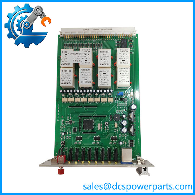
CS-TX3-3.81X2.54-64TW
Key Features and Advantages
Self-describing configuration, which is what actually protects the buyer: the string states pitch, way count and wiring convention, so a replacement can be checked with a ruler and a look at the connector rather than with a drawing that does not exist. On a passive board, physical fit is the whole specification — if the front blocks land on 3.81 mm centres and the back header is the right 64-way, the board will work.
Connectorised field wiring in one operation: sixty-four circuits leave the cabinet through a single back connector instead of 128 individually landed wires. For a plant doing a loop check or a cabinet modification, that is the difference between a planned outage and an unplanned one, and it is the reason the original designers put a marshalling layer in at all.
Direct board-to-board mating: the back connector plugs into the I/O board without an intermediate cable, removing a connector pair and a length of harness from every channel. Fewer interfaces means fewer intermittent faults that present as sensor failures.
Passive by design, so failure modes stay simple: no amplifier to drift, no isolated supply to collapse, no firmware to corrupt. When one of these boards fails it fails as an open, a short or a cracked joint — all of which are locatable with a meter, unlike the failures of the active boards around it.
Per-channel RC conditioning where it exists at all: a filter on each way suppresses contact bounce and pickup on long field runs, which is useful on breaker position and limit switch inputs that share a cabinet with contactor coils. Note the trade-off — a filter that slows an edge changes the timing the I/O board sees, and on sequence-of-events inputs that matters.
Honest limits: this designation has one market source, no OEM drawing and no published pin-out. Electrical ratings above are what the supplier states, not what Alstom published, and should be treated as indicative until proved on the bench. A buyer who needs traceability should specify by physical configuration and insist on a pin-to-pin comparison against the board being replaced.
Applications
ALSPA P320 cabinet field-wiring layer: in thermal, hydro and combined-cycle unit control cabinets of the Alstom power automation generation, the marshalling board sits between the plant’s field terminals and the acquisition boards. CS-TX3-3.81X2.54-64TW is the interface at which breaker position, valve limit switches, interlock contacts and status indications become a connectorised bundle for the I/O electronics.
Loop checking and cabinet refurbishment: when a cabinet’s field wiring is re-landed, upgraded or re-terminated during a life-extension programme, the marshalling board is what keeps the work contained. Replacing 128 screw connections with one 64-way connector is a maintenance-planning decision as much as an electrical one.
Fault isolation between field and electronics: a passive board provides a clean break point. Disconnecting the back connector separates the entire field side from the acquisition side in one action, which is how a technician decides in minutes whether a persistent input fault lives in the plant or in the cabinet.
Retrofit spare holding: cabinets of this generation are supported by dismantled and refurbished stock rather than by current production, and the marshalling layer is the most physically exposed part of the rack. Holding one verified spare per cabinet, with its pin mapping recorded, is cheaper than discovering the mapping problem during an outage.
Where it does not fit: any application described in terms of active signal conversion, isolated transmitters, protocol gateways, traction converters or 3 kV supplies. This is a passive wiring interface, and boards sold under those descriptions belong to different product lines.
Related Products
CMP1838 (TRVCO62345000 / CP00005202) — the control board in the same cabinet; the role this board serves is to feed the acquisition electronics around it. STO1726KO1 (4022.437.1856) — digital input/output board used in the same ALSPA P320 cabinet and mated through this class of marshalling hardware. MC1AB37 — DI/DO acquisition board referenced in the same cabinet listings; note that the same 4022.437.1856 number is attached to both this board and STO1726KO1 by the same source, so the number alone cannot identify either. N895609510K — ALSPA P320 central processing assembly (carrier board with mezzanine sub-modules); a different CPU build of the same platform. ALSPA P320 rack and backplane assemblies — the mechanical and bus infrastructure both the control and I/O boards depend on. 3.81 mm pluggable terminal blocks and 64-way 2.54 mm headers — the commodity components the designation is actually built from; the practical cross-reference when no drawing exists.
Installation and Maintenance
Before installation: do not order on the designation alone. Record the physical configuration of the board being replaced — front terminal block pitch, back connector type and way count, board outline, mounting rail position, and above all the pin-to-pin mapping between a front way and its back connector position. Photograph the old board fully populated with its wiring, because a marshalling board is defined by its mapping, and two boards that look identical can land channel 17 on a different pin. Confirm the cabinet file references — the CMP1838 control board and its acquisition boards — so the replacement is verified against the plant’s own documentation rather than the supplier’s description.
Installation: isolate the cabinet and verify dead before touching terminals; on a passive board there is no indication that the field side is live, which is precisely why this step cannot be skipped. Land field wires one circuit at a time against the photographed record, keeping two-wire pairs on adjacent ways, and terminate to the block manufacturer’s torque rather than to feel. Seat the back connector fully — a partially engaged 64-way header produces intermittent faults across many channels at once and is routinely misdiagnosed as multiple field failures. Label the board with its date of fit and mapping revision.
Maintenance: inspect front blocks annually for loose terminations and for the corrosion that follows a humid cabinet; a marshalling board fails far more often at a terminal than in its copper. Where per-channel filters exist, remember they alter input timing — if a sequence-of-events record shifts after a board change, suspect the filter rather than the field device. Keep one verified CS-TX3-3.81X2.54-64TW spare per cabinet with its mapping sheet, and re-verify that mapping at each outage rather than trusting a label applied a decade ago.
Warranty and Quality
Every CS-TX3-3.81X2.54-64TW board is supplied as a 64-channel passive signal transfer board for ALSPA -generation cabinets and is identified by physical configuration — way count, terminal pitch, back connector type and board outline — before dispatch, with a pin-to-pin continuity record taken across all 128 terminations and supplied with the unit. Boards are inspected for terminal block condition and thread integrity, back connector wear and contact deformation, PCB damage on both sides, and evidence of prior rework; the designation is stated honestly as a supplier-composed reference rather than an Alstom drawing number. A 12-month repair, replacement or refund commitment applies. Technical support covers what this part actually requires: decoding CS-.81X2.54-64TW into its construction specification, explaining why the sibling 4022.437.1856 number cannot identify either of the two boards it is attached to, and helping a plant record the mapping that makes a passive board replaceable at all.