Description
Product Overview
The CTC SC203-100A-002IR-010-01K-05 is a field-configurable signal conditioner from the CTC SC200 Series, designed to translate vibration measurements into process-control signals that can be understood by a PLC, DCS, SCADA system, or conventional vibration data-acquisition equipment. The exact stock configuration uses a 100 mV/g acceleration input, a 0–2 in/s RMS full-scale range, and filtering from 10 Hz to 1000 Hz. Standard outputs are 4–20 mA and 0–5 VDC.
For CTC SC203-100A-002IR-010-01K-05, the part-number configuration is more informative than simply calling it a “vibration module.” The SC200 platform accepts acceleration, velocity, temperature, and displacement-related sensor signals depending on configuration, while internal DIP switches allow field adjustment of input selection, scaling, filtering, and output functions. The conditioner can also provide sensor excitation, with the published SC200 specifications identifying 24 VDC, 4 mA DC sensor excitation and selectable sensor power.
The CTC SC203-100A-002IR-010-01K-05 is therefore best understood as the signal-processing layer between a vibration sensor and the plant control system. Its standard configuration provides a practical way to bring vibration amplitude into a control-room environment without requiring operators to interpret raw accelerometer signals. A 4–20 mA output can be sent to a PLC/DCS analog input, while the voltage output and buffered signal provide additional access for vibration analysis. For replacement work, the exact configuration must be preserved; a similar SC200 unit with a different full-scale range or filter can change the meaning of the process signal.
Product Introduction
Raw vibration signals are useful to vibration specialists but are not directly convenient for most control-system analog inputs. CTC SC203-100A-002IR-010-01K-05 converts a 100 mV/g acceleration signal into standard process outputs, with a 0–2 in/s RMS configured range and 10–1000 Hz filtering.
For a vibration monitoring system replacement, the configuration code matters. The unit is field configurable, so two SC200 conditioners with similar housings can produce different engineering-unit ranges, filters, or output behavior.
Key Technical Specifications
| Parameter | Value |
|---|---|
| Manufacturer | CTC / Connection Technology Center |
| Model | SC203-100A-002IR-010-01K-05 |
| Product Family | SC200 Series |
| Product Line | PRO Line |
| Product Type | Vibration & Temperature Signal Conditioner |
| Input Type | Acceleration |
| Input Sensitivity | 100 mV/g |
| Full-Scale Range | 0–2 in/s RMS |
| Frequency Filter | 10–1000 Hz |
| Standard Analog Output | 4–20 mA |
| Voltage Output | 0–5 VDC |
| Buffered Output | BNC jack and screw terminals |
| Sensor Excitation | 24 VDC, 4 mA DC |
| Input Power | 24–32 VDC unregulated |
| Maximum Conditioner Current | 225 mA |
| Maximum Load Resistance | 600 Ω |
| Isolation | 1000 VDC |
| Mounting | 35 mm DIN rail |
| Connectors | Detachable screw terminals |
| Humidity | 0–95% RH, non-condensing |
| Ambient Temperature | −40°C to +85°C |
| Configuration | Internal DIP switches / field configurable |
The exact standard configuration and electrical specifications are documented in CTC catalog material and configuration documentation.
Important identification point: Some online listings incorrectly describe this exact part as a generic temperature controller or an 8-channel industrial control module. The catalog identifies SC203-100A-002IR-010-01K-05 as a vibration/temperature signal conditioner, with the specific standard configuration shown above.
Related Products
- SC203 Series — Same basic signal-conditioning architecture with different input, range, filter, and output configurations. The exact suffix determines the configured measurement characteristics.
- — The broader CTC signal-conditioner family. Units can process acceleration, velocity, temperature, or displacement-related signals depending on the selected configuration.
- SC207 Series — Another -family configuration used for vibration signal conditioning. It can be configured with different input sensitivities and engineering ranges.
- SC206 Series — Related vibration/temperature signal conditioner configuration for applications requiring different signal ranges or filtering.
- SC208 Series — -family conditioner for alternate sensor and measurement configurations; selection should follow the required input and output scaling.
- — The exact stock configuration, rather than merely a generic replacement. This distinction matters because the platform is field configurable.
- CTC Piezoelectric Accelerometers — Compatible sensor category for applications using acceleration input. The sensor’s sensitivity must match the conditioner configuration.
- PLC/DCS Analog Input Module — Receives the ‘s 4–20 mA process signal for alarm, trending, interlock, or condition-monitoring logic.
- Conventional Vibration Data Acquisition System — Can use the conditioner’s buffered signal for dynamic vibration analysis while the 4–20 mA output feeds the control system.
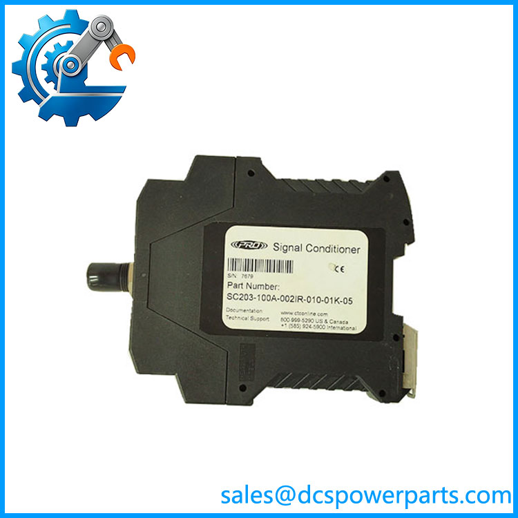
SC203-100A-002IR-010-01K-05
Frequently Asked Questions
What is CTC used for?
The CTC is a vibration signal conditioner.
Its standard configuration takes a 100 mV/g acceleration input, processes it over a 0–2 in/s RMS full-scale range, and provides standardized outputs for plant control and monitoring.
Typical applications include:
- Rotating-equipment monitoring
- Pumps and motors
- Fans and blowers
- Gearboxes
- Process machinery
- PLC/DCS condition monitoring
- Vibration alarm systems
What does 100A-002IR mean in the part number?
The configuration code carries useful engineering information.
For this exact standard configuration:
- 100A corresponds to the 100 mV/g acceleration input.
- 002IR identifies the configured 0–2 in/s RMS range.
- 010 corresponds to the 10 Hz high-pass/filter configuration shown in the CTC selection information.
- The complete suffix establishes the remaining output/power configuration.
The exact code should be checked against the CTC configuration table before modifying DIP switches. The documentation explicitly states that not all configuration combinations are compatible.
Can I connect the directly to a PLC or DCS?
Yes, through its process-control output.
The documentation specifies a 4–20 mA output for vibration and temperature signals, intended specifically for connection to PLC, DCS, or SCADA systems. It also provides a selectable voltage output for vibration applications.
A typical arrangement is:
Accelerometer → conditioner → 4–20 mA → PLC/DCS analog input
The scaling configured in the PLC/DCS must match the range configured inside the .
Can I hot-swap this signal conditioner?
I would not treat it as a hot-swappable module.
The has a 24–32 VDC power connection and external sensor wiring. Although its detachable terminals simplify maintenance, the published documentation does not establish hot-swap operation.
For replacement:
- Isolate the 24 VDC supply.
- Record all terminal connections.
- Verify DIP-switch positions.
- Install the replacement.
- Confirm sensor excitation.
- Verify the 4–20 mA output.
- Confirm PLC/DCS engineering-unit scaling.
Will replacing change my vibration alarm settings?
It can, if the replacement is configured differently.
The family is field configurable for input signal, scale values, filtering, and output functions.
For a direct replacement, compare:
- Sensor sensitivity
- Full-scale range
- Filter settings
- 4–20 mA scaling
- Voltage output
- Sensor excitation
- DIP-switch positions
If these match, the PLC/DCS alarm thresholds normally do not need to be redesigned.
Does support firmware v3.1?
Firmware v3.1 is not the appropriate compatibility criterion for this device.
The is a signal-conditioning instrument configured through its hardware settings rather than a PLC CPU with user application firmware. Compatibility should instead be established from the part-number configuration, sensor type, input sensitivity, measurement range, filtering, output type, and power requirements.
If the feeds a PLC/DCS, firmware compatibility belongs to the receiving controller and its analog-input module.
How sho verify a New Surplus ?
A visual inspection is not enough because the is configurable.
I would request:
- Exact part-number photograph
- Serial number
- Configuration/DIP-switch record
- 24 VDC power test
- Sensor excitation measurement
- Known-input signal test
- 4–20 mA output verification
- 0–5 VDC output verification
- Filter-response check
- Isolation test where applicable
- Terminal and connector inspection
- Final test report
For this particular unit, I would pay special attention to the 100 mV/g input and 0–2 in/s RMS range. A replacement with the wrong configuration may power up normally and still deliver an incorrectly scaled vibration signal to the DCS.