Description
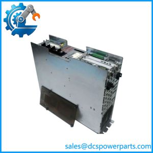
Bosch Rexroth HMV01.1R-W0045-A-07-NNNN Regenerative Supply Unit
Product Overview
The Bosch Rexroth HMV01.1R-W0045-A-07-NNNN is a regenerative HMV supply unit in the IndraDrive M drive system. Material number R911296725 identifies this specific configuration. Its job is fundamentally different from that of an individual servo amplifier: it supplies the common DC bus used by the associated drive system and manages energy flow between the AC mains and the DC link. The “R” configuration identifies the regenerative supply architecture, allowing suitable braking energy from the drive system to be returned toward the mains rather than relying solely on dissipation through a braking resistor.
For multi-axis machinery, that architecture is useful because several servo drives can operate from a shared DC bus while the HMV supply handles the mains interface. The documented unit accepts 3-phase 380–480 VAC at 50–60 Hz, provides a nominal 700 VDC bus, and is rated at 45 kW output. Internal air cooling with an integrated blower removes heat from the power section, while the enclosure rating is IP20.
The Bosch Rexroth HMV01.1R-W0045-A-07-NNNN therefore belongs in the power-supply layer of an IndraDrive M multi-axis system rather than the motion-control layer. Servo amplifiers connected to the common bus still determine individual motor control. During replacement, engineers should check the complete IndraDrive power topology, mains choke/transformer requirements, DC-bus loading, braking configuration, and connected drive ratings. A 45 kW nameplate match by itself is not sufficient evidence that two HMV units are interchangeable. The unit’s documented product status is also relevant for legacy procurement: one service source lists an end-of-production date of December 31, 2025.
Product Introduction
Multi-axis IndraDrive installations often depend on a central supply unit rather than giving every servo axis its own mains converter. The HMV01.1R-W0045-A-07-NNNN provides that shared 700 VDC bus at a rated 45 kW while supporting regenerative operation.
For a legacy replacement, the important checks extend beyond the model number: verify the R911296725 material number, regenerative configuration, 380–480 VAC supply, connected DC-bus load, mains interface components, and cooling arrangement before committing to installation.
Key Technical Specifications
| Parameter | Value |
|---|---|
| Product Model | HMV01.1R-W0045-A-07-NNNN |
| Material Number | R911296725 |
| Manufacturer | Bosch Rexroth Indramat |
| Product Family | IndraDrive M / HMV |
| Product Type | Regenerative Supply Unit / Power Stage |
| Supply Configuration | Regenerative |
| AC Input | 3-phase 380–480 VAC |
| Mains Frequency | 50–60 Hz |
| Rated Output Power | 45 kW |
| Nominal DC-Bus Voltage | 700 VDC |
| DC-Bus Capacity | 1.88 mF |
| External Control Voltage | 24 VDC ±5% |
| Cooling | Internal air cooling with integrated blower |
| Protection Rating | IP20 |
| Permanent Braking Power | 0.4 kW |
| Maximum Braking Power | 90 kW |
| Maximum Power with Power Choke | 112 kW |
| Continuous Power Without Choke | 27 kW |
| Continuous Power with Power Choke | 45 kW |
| Listed Continuous Mains Current | Approximately 65 A |
| Weight | Approximately 20–22 kg |
The published commercial technical records give slightly different weight figures, approximately 20 kg and 22 kg, so the exact shipping/assembly weight should be verified from the nameplate or original mechanical documentation.
Major Features / Practical Advantages
45 kW regenerative supply
The principal function is the 45 kW regenerative supply. During deceleration, suitable drive-system energy can be transferred back toward the AC supply rather than being handled solely through resistor-based dissipation. That makes the HMV “R” version fundamentally different from an HMV “E” non-regenerative supply.
For machine builders, the distinction affects both electrical design and heat management. A regenerative architecture can reduce the amount of braking energy that must be converted into heat at the machine cabinet, but it introduces additional mains-side engineering requirements.
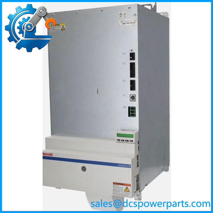
HMV01.1R-W0045-A-07-NNNN
700 VDC common DC bus
The HMV unit establishes a nominal 700 VDC DC bus for the associated IndraDrive system. Individual servo drives then use this shared DC-link infrastructure for their power stages.
This common-bus approach is particularly relevant to multi-axis machinery. Replacing the supply unit therefore requires checking the total connected drive load rather than looking at one servo amplifier in isolation.
380–480 VAC three-phase input
The documented mains input is 3-phase 380–480 VAC at 50–60 Hz. The power infrastructure upstream of the HMV should be checked for the appropriate transformer, mains choke, protection, grounding, and EMC arrangement specified for the complete IndraDrive installation.
Do not treat the HMV as a generic 480 VAC power converter. Its installation is tied to the IndraDrive system design.
Internal blower cooling
The unit uses internal air cooling with an integrated blower. Cabinet airflow, ambient temperature, filter condition, and fan operation therefore matter during troubleshooting and replacement.
A replacement unit that electrically matches the old one can still fail prematurely if the cabinet’s cooling path has deteriorated. In older machines, inspect the surrounding cabinet ventilation at the same time.
Regenerative energy handling
The HMV01.1R configuration is designed for regenerative operation. The available braking-power figures are substantially higher than the unit’s continuous output rating, so braking events must be evaluated according to duration, repetition rate, connected drives, braking components, and the complete power-system design.
The 90 kW maximum braking-power figure should not be interpreted as a continuous 90 kW supply capability. It describes a braking-related operating limit under specified conditions.
24 VDC control supply
The documented external control voltage is 24 VDC ±5%. This is separate from the high-voltage mains and DC-bus power path and should be checked during commissioning and fault diagnosis.
A missing or unstable control supply can prevent an otherwise healthy power stage from entering the expected operating state.
Legacy IndraDrive M architecture
The .1R belongs to the older IndraDrive M supply-unit family. The unit is therefore most relevant to maintenance and replacement of existing multi-axis machines rather than to assuming compatibility with every later Rexroth drive family. A current-generation drive system should be evaluated against its own supply-unit architecture before considering an HMV replacement.
Related Products
- .1E-W0030-A-07-NNNN — 30 kW non-regenerative HMV supply variant. Its electrical architecture differs from the regenerative .1R.
- .1E-W0075-A-07-NNNN — 75 kW HMV supply for higher-power IndraDrive configurations.
- .1E-W0120-A-07-NNNN — 120 kW non-regenerative HMV supply for larger multi-axis installations.
- .1R-W0120-A-07-NNNN — 120 kW regenerative HMV supply, intended for higher-power regenerative applications.
- .1R-W0018-A-07-NNNN — Lower-power 18 kW regenerative HMV configuration.
- HMS / HMD drive units — IndraDrive M servo-drive power stages that use the common DC-bus supply rather than replacing the HMV supply function.
- R911296725 — The Bosch Rexroth material number corresponding specifically to .1R-W0045-A-07-NNNN. This number is useful when verifying inventory and replacement documentation.
FAQ
Is .1R- a servo drive?
No. It is a regenerative supply unit/power stage. Its primary role is to provide the common DC-bus power infrastructure for an IndraDrive M system. Individual servo drive modules perform the actual motor-control function.
What is the DC-bus voltage?
The documented nominal DC-bus voltage is 700 VDC. This is a high-voltage DC link and must be treated accordingly during isolation, discharge, measurement, and maintenance procedures.
Can I replace the .1R with an .1E?
Not as a simple drop-in substitution. The R version is regenerative, whereas the E version represents a different supply/braking architecture. The complete machine power design, braking method, drive configuration, and system documentation must be checked before considering such a substitution.
Can I hot-swap this power supply?
No general hot-swap assumption should be made. This is a high-voltage mains/DC-bus power unit, not a plug-in control I/O module. Replacement requires the approved IndraDrive shutdown, isolation, DC-bus discharge, verification, and commissioning procedure for the machine.
Does this support firmware v3.1?
The model number alone does not establish a firmware revision. Compatibility should be checked using the complete IndraDrive system configuration and the documentation for the associated control and drive components.
What is the maximum output power?
The documented rated output power is 45 kW. The specification also lists 27 kW continuous power without a choke and 45 kW continuous power with a power choke under the specified conditions. Those figures should not be confused with the 90 kW maximum braking-power figure.
What input voltage does the .1R- require?
The documented mains supply is 3-phase 380–480 VAC, with a nominal frequency of 50–60 Hz. The upstream transformer/choke and protection arrangement must be compatible with the complete IndraDrive installation.
Is the unit still a current-production product?
Available lifecycle information indicates that this particular .1R configuration reached end of production on December 31, 2025. That makes revision and condition verification particularly important when sourcing a replacement for an operating legacy machine.
Procurement Note
For a Bosch Rexroth .1R- replacement, match the complete type code and R911296725 material number wherever possible. Confirm the regenerative configuration, 45 kW rating, 380–480 VAC input, 700 VDC DC bus, external 24 VDC control supply, cooling arrangement, and connected IndraDrive M axis configuration.
Pay particular attention to the distinction between and . The first is regenerative; the second is a different supply architecture. Treating them as equivalent because both generate a nominal 700 VDC bus can lead to a significant system-design error.
For legacy spare procurement, inspect the actual nameplate, power terminals, DC-bus terminals, cooling fan, and enclosure condition. If the offered unit is refurbished, ask whether the blower, capacitors, power semiconductors, and protection circuits were tested under load. For a 45 kW high-voltage supply, a basic power-on test is not the same as a meaningful functional test.