Description
Product Introduction
A generator protection relay has to distinguish an actual electrical fault from an abnormal operating condition without creating unnecessary trips. Incorrect protection settings, mismatched current-transformer inputs, or missing optional functions can leave a generator inadequately protected—or cause avoidable shutdowns. The Beckwith Electric M-3425A is an integrated digital generator protection relay intended for generators across a range of ratings and prime-mover types.
For plant engineers and maintenance buyers, the important procurement detail is the ordered configuration, not just the model number. Differential protection, optional ground-fault functions, expanded I/O, communications, and HMI accessories should be checked against the existing protection scheme. When sourcing a Beckwith Electric M-3425A replacement relay, request configuration details and test evidence before treating it as ready for installation.
Key Technical Specifications
| Parameter | Details |
|---|---|
| Model | M-3425A |
| Manufacturer | Beckwith Electric |
| Product Type | Digital generator protection relay |
| Primary Application | Generator electrical protection and monitoring |
| Protection Architecture | Multifunction, configurable protection elements |
| Current Inputs | CT secondary options include 1 A or 5 A variants; verify the specific unit |
| Voltage Inputs | Configured for the installation’s voltage-transformer arrangement |
| Protection Functions | Includes generator protection elements such as differential, overcurrent, voltage, frequency, and loss-of-field protection, subject to configuration |
| Event Recording | Sequence-of-events log with 1 ms time resolution; stores up to 512 recent events |
| Communications | Serial communications; optional Ethernet supports Modbus TCP/IP and BECO2200 over TCP/IP |
| Time Synchronization | IRIG-B input supported |
| Mounting | Panel / rack-style mounting |
| Optional Accessories | M-3925A Target Module, M-3931 HMI, and other configuration-dependent accessories |
| Environmental Conditions | Refer to the applicable hardware documentation and installation requirements |
| Supply and I/O Configuration | Confirm from the unit nameplate and ordered configuration |
Procurement caution: Do not assume every M-3425A includes every protection element, Ethernet, expanded I/O, or optional accessory. Confirm the complete configuration record and firmware version before approving a replacement.
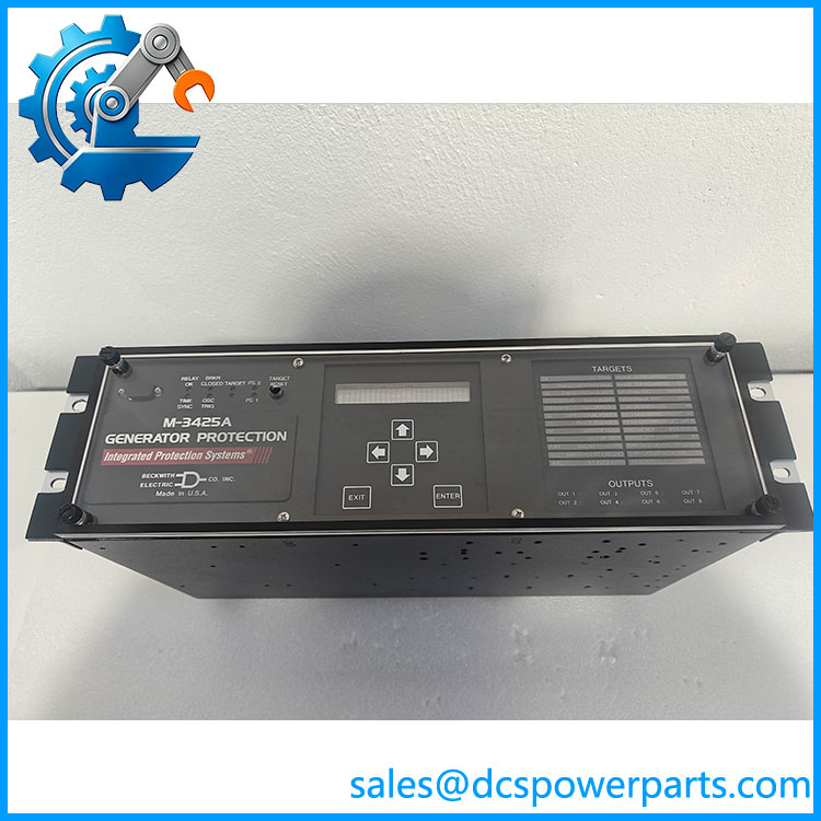
M-3425A
Application Scenarios & Pain Points
Generator protection failures can have consequences well beyond a relay alarm. A missed fault may damage equipment, while an incorrect pickup or timing setting can disconnect a generator during a disturbance it should have ridden through.
- Power generation plants: Protect generators against electrical faults and abnormal operating conditions using the functions enabled in the relay configuration.
- Industrial captive-power systems: Coordinate generator protection with transformers, switchgear, bus protection, and upstream relays.
- Generator refurbishment projects: Replace aging protection hardware while preserving the intended protection philosophy and documenting any configuration changes.
- Fault investigation: Use event records, measured values, and oscillographic data to help identify the sequence leading to a trip or abnormal operating condition.
Field case: If a generator trips immediately after relay replacement, do not assume the new relay is defective. Compare CT ratios, VT wiring and phase rotation, nominal system settings, active protection elements, and output-contact assignments against the approved settings record first.
Related Products
These Beckwith Electric models are associated accessories or complementary protection products. They are not universal drop-in replacements for the M-3425A.
- M-3925A Target Module — Optional target indication module used with supported M-3425A configurations.
- M-3931 HMI Module — Optional human-machine interface for local operator interaction and display.
- M-3921 Field Ground Coupler — Associated with supported field-ground protection applications; verify the protection function and wiring requirements.
- M-3948 Redundant High Voltage Power Supply — Optional power-supply accessory for supported configurations.
- M-3949 Redundant Low Voltage Power Supply — Alternative power-supply option for compatible configurations.
- M-3801D IPSplot Plus — Oscillographic analysis software for examining recorded disturbance data.
- S-3400 IPScom Communications Software — Configuration and communications software identified in the M-3425A documentation.
Engineer’s Guide: Field Pitfalls to Avoid
1. Assuming the replacement has the same protection options
Two units with the same base model may differ in optional protection elements, I/O, communications, or hardware configuration.
Avoid it: Compare the existing relay’s configuration record, installed options, firmware, and accessory modules against the proposed replacement. Confirm optional functions—especially specialized ground-fault protection—before ordering.
2. Transferring settings without checking CT and VT circuits
A settings file alone cannot correct a physical mismatch in current-transformer ratio, voltage-transformer wiring, phase assignment, or grounding arrangement.
Avoid it: Validate input ratings and wiring diagrams, then perform approved secondary-injection and functional tests. Check differential protection polarity and stability before enabling trip outputs.
3. Returning the generator to service without validating trip logic
Protection pickup tests do not necessarily prove that the complete trip path works. Incorrect output mapping, breaker interface wiring, or blocking logic can defeat otherwise correct relay settings.
Avoid it: Test the full protection chain, including relay outputs, lockout logic, breaker trip circuits, alarms, and event recording. Follow the plant’s approved commissioning procedure and document test results before energizing.
Frequently Asked Questions
Q1: What is the Beckwith Electric M-3425A used for?
It is a multifunction digital generator protection relay used to detect electrical faults and abnormal operating conditions. Its enabled protection functions depend on the ordered configuration and settings.
Q2: Can an M-3425A replace an existing generator protection relay directly?
Not without an engineering review. Verify the current and voltage input ratings, protection functions, trip and alarm logic, communications, panel connections, and approved settings. A matching model number does not eliminate the need for commissioning tests.
Q3: Does every M-3425A support Ethernet communications?
No. The documentation identifies Ethernet as an optional feature. When present, it supports Modbus TCP/IP and BECO2200 over TCP/IP. Confirm the installed communications hardware and required protocol before assuming network compatibility.
Q4: How can I verify the condition and authenticity of a replacement unit?
Request photographs of the actual unit and nameplate, its complete configuration and option details, serial identification, and documented inspection or test results. For a used or refurbished relay, ask specifically whether the unit has passed functional testing and whether its accessories are included.
Q5: What tests should be completed before commissioning?
At minimum, use an approved test plan to verify input scaling, protection pickup and timing, enabled protection elements, trip-output logic, alarms, communications where applicable, and event recording. Include end-to-end breaker trip checks as required by the plant’s procedures.
Q6: What information should I provide when requesting a quotation?
Provide the complete model number, unit configuration, CT and VT input requirements, required protection options, communications requirements, and accessory list. Include the required quantity and delivery deadline, and specify whether you need a new unit or will consider tested surplus or refurbished stock.
Q7: What are the lead time and warranty for the M-3425A?
These depend on the supplier’s actual inventory, unit condition, and commercial terms. Request written confirmation of stock status, dispatch timing, warranty duration, return conditions, and the test documentation supplied with the unit before placing an order.