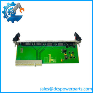
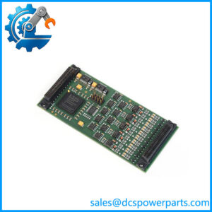
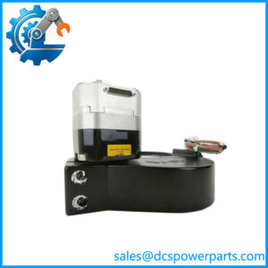
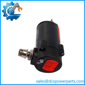
Description
Beckhoff CX1100-0001
Key Technical Specifications
| Parameter | Specification |
|---|---|
| Product Model | CX1100-0001 |
| Manufacturer | Beckhoff Automation |
| Product Family | CX1000 / CX1010 / CX1020 |
| Product Type | Power supply module |
| Input Voltage | 24 VDC |
| Permitted Voltage Range | -15% / +20% |
| Maximum Power Consumption | 2.5 W |
| Dielectric Strength | 500 V RMS, supply/internal electronics |
| Recommended Fuse | 4 A at 24 VDC |
| Connection | 1 × 5-pin open pluggable connector |
| PC/104 System Supply | 24 VDC supplied to other CX system components |
| K-bus | None |
| E-bus | None |
| IP-Link | None |
| I/O-DPRAM | None |
| NOVRAM | 8 kB |
| Display | Illuminated FSTN, 2 × 16 characters |
| Diagnostic LED | 1 × PWR |
| Dimensions | 45 × 100 × 91 mm |
| Weight | Approx. 180 g |
| Operating Temperature | 0 to +55°C |
| Storage Temperature | -25 to +85°C |
| Relative Humidity | 95%, non-condensing |
| Protection Rating | IP20 |
Beckhoff specifies the CX1100-0001 as a power supply without an I/O interface. The module supplies the remaining CX system components through the internal PC/104 bus, while its own additional functions include the display, navigation switch, and nonvolatile RAM.
Product Introduction
The Beckhoff CX1100-0001 is the basic power supply module for compatible CX embedded PC configurations. It accepts a 24 VDC control-panel supply and distributes system power through the internal PC/104 architecture. Unlike CX1100 variants equipped with K-bus, IP-Link, or E-bus interfaces, the CX1100-0001 has no local I/O interface.
The module also provides a 2 × 16-character illuminated display, navigation switch, 8 kB NOVRAM, and PWR diagnostic LED. Beckhoff identifies the -0001 as being in the service phase, so it is particularly relevant when maintaining installed CX1010/CX1020 equipment rather than designing a new controller platform.
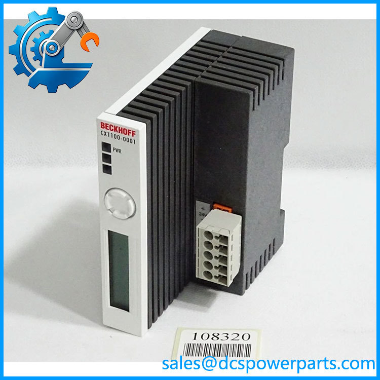
CX1100-0001
Application Scenarios & Field Pitfalls — The Engineer’s Perspective
Engineering Pain Point
The most common replacement mistake is treatin as an ordinary 24 VDC power supply. It is actually a mechanically and electrically integrated CX system module. The 24 VDC input feeds the CX stack through the internal PC/104 connection, and the module also carries system functions such as NOVRAM and the display. Replacing it with another variant changes the I/O architecture, not just the power arrangement.
Typical Applications
- CX1010 controller systems requiring the basic 24 VDC power module without local I/O.
- CX1020 embedded PC systems using external or separate I/O/fieldbus interfaces.
- Legacy TwinCAT PLC installations where the existing CX hardware must remain in service.
- Maintenance replacement where the ori has developed a power, connector, display, or NOVRAM-related fault.
Technical Pitfalls to Avoid
- Do not substitute -0002 automatically.
The -0002 adds a K-bus interface, while the -0001 intentionally has no I/O interface. Beckhoff states can be replaced in the field by -0002 when local Bus Terminal I/O is required, but that is an architectural change rather than a like-for-like identification. - Check the 5-pin connector wiring.
Beckhoff documents pin 1 as +24 VDC, pin 2 as 0 VDC, pin 3 as ground, with pins 4 and 5 reserved. Older versions may have different labeling around unused UPS connections; those terminals should not simply be repurposed. - Respect the voltage range.
The specified supply is 24 VDC with -15%/+20% tolerance. A nominally correct 24 VDC source can still create problems if the actual cabinet supply falls outside the permitted range under load. - Check the entire CX stack before replacement.
The power module interfaces directly with the CPU/system modules. Confirm the installed CPU, system interface, fieldbus modules, and physical stack arrangement before ordering. - Do not confuse the module’s display with an HMI.
The 2 × 16-character display is intended for system and user messages and is part of the CX power-module architecture; it is not a general-purpose operator interface. - Check service-phase status.
Beckhoff currently list as a service-phase product. For an installed machine, maintaining the exact module can be preferable to changing the controller architecture without a validated migration plan.
Related Products
- — Power supply with K-bus interface for Beckhoff Bus Terminals; not equivalent to the I/O-free -0001 configuration.
- — Power supply with K-bus and IP-Link interfaces for local I/O and Fieldbus Box expansion.
- — Power supply with E-bus interface for EtherCAT Terminals; intended for compatible CX1020/CX1000/CX1010 CPU configurations.
- CX1020 — Embedded PC CPU family that uses -series power modules as part of its system architecture.
- CX1010 — Earlier CX Embedded PC family documented wit power supply.
- -0012 / -0013 / -0014 — Related power-supply variants associated with CX1030 systems; their electrical and interface configuration should not be assumed interchangeable with the -0001.
Procurement Note
For a replacement, specify the complete designation and verify the CPU module it is connected to, especially whether the system is a CX1010 or CX1020 installation. Confirm the 24 VDC cabinet supply, connector condition, physical module dimensions, and whether the existing system actually requires an I/O-equipped variant.
The critical point is simple: is the no-I/O-interface power-supply version. If the existing machine uses Bus Terminals, IP-Link, or EtherCAT terminals directly through the power module, verify the installed variant before purchasing.