Description
Product Overview
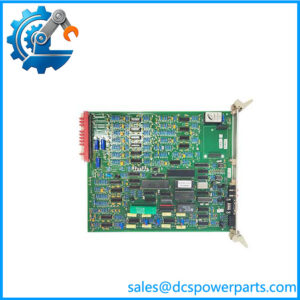
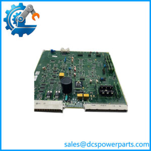
AL129A is the integrated power supply of the Alstom ALSPA CE2000 and CE3000 controller families — the rack-mounted chopper converter that turns a wide-range single-phase AC feed into the isolated +5 V and +12 V rails every card in the rack runs on. It is not a signal board, not a CPU, and not a relay module: it is a black 5 cm-wide cassette with an extractor handle, an ON/OFF switch, two LEDs marked +5V and +12V and a mains connector on the front, plugged into the FB178 backplane of an AM163, AM164 or AM166 rack, in single or redundant configuration.
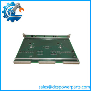
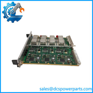
The module exists under three identifiers, which is the first practical problem a buyer meets. The product name is AL129A; the OEM part number silk-screened beside it is CD101152, with a board revision letter such as D3; and Alstom’s internal ordering code is U0100050, printed on a separate label. A search for one of those strings returns almost nothing, and the pages that do return usually describe the part as a rail-transit control module, a vibration monitoring card, or a SIL 3 safety relay module — all of which the photographs of the actual unit contradict. Nothing about the hardware supports those claims; it is a power supply.
The converter behind the Alstom badge is a Martek Power design: the nameplate and the board inside both carry the Martek mark, and the topology visible on the board is a modern one for its generation — an active power-factor-corrected front end producing a roughly 380 V intermediate bus, followed by two flyback converters, one per output rail, each with its own PWM controller. That architecture is why the module tolerates anything from 96 to 253 VAC without a tap change, and why its outputs are trimmed deliberately high: on a tested unit the +5 V rail reads 5.70 V at no load and 5.43 V at the full 10 A, and the +12 V rail 12.26 V falling to 12.06 V at 4 A. The margin is there so that backplane and cable drop at full load still land the rail inside the logic supply window.
The reason this part matters is simple: it is the single point that takes an entire ALSPA CE2000 cabinet down. The rack’s own diagnostics detect the loss of one supply and raise a redundancy fault while the other carries the load — a behaviour that was verified on an Alspa test bench, not merely specified. Every other card in the rack can be swapped from spares; if the power supply is missing, the cabinet is dark. That is why, two decades after the last units left the factory, AL129A is still sourced — as tested refurbished stock, against the original Alstom code, for turbines and plant control systems that are not going to be migrated this year.
Technical Specifications
| Parameter | Value |
|---|---|
| Model / OEM part / Alstom code | AL129A / CD101152 (revision letter e.g. D3) / U0100050 |
| Manufacturer | Alstom (Alspa / Cegelec), converter built by Martek Power |
| Product type | Integrated power supply, AC-input chopper converter, rack cassette |
| Input | 96–253 VAC, 50 Hz, single phase |
| Outputs | Isolated +5 V / 10 A and +12 V / 4 A (≈ 120 W total) |
| Input fuses | F1 = F2 = T3,15A (time-lag, 3.15 A) |
| Measured output (tested unit, 242 VAC in) | +5 V: 5.70 V no load / 5.50 V at 5 A / 5.43 V at 10 A; +12 V: 12.26 V no load / 12.11 V at 2 A / 12.06 V at 4 A |
| Overload behaviour | 5 V rail trips at ≈ 12.8 A, 12 V rail at ≈ 5.5 A; output LED extinguishes on trip; automatic recovery when load normalises |
| Power train | Active PFC front end (≈ 380 V intermediate bus) + separate 5 V and 12 V flyback converters |
| Rack / backplane | AM163, AM164, AM166 CE2000 racks; FB178 backplane; single or redundant configuration |
| Indication / controls | Front ON/OFF switch, +5V and +12V LEDs, mains connector, extractor handle |
| Dimensions / weight | 265 × 50 × 265 mm; approx. 2.02 kg |
| Thermal (tested unit) | Hot-spot ≈ 64 °C at no load, ≈ 71.5 °C at 5 V maximum load; convection cooled |
| Marking / origin | CE; nameplate examples marked Made in Tunisia, date code 2006/36 |
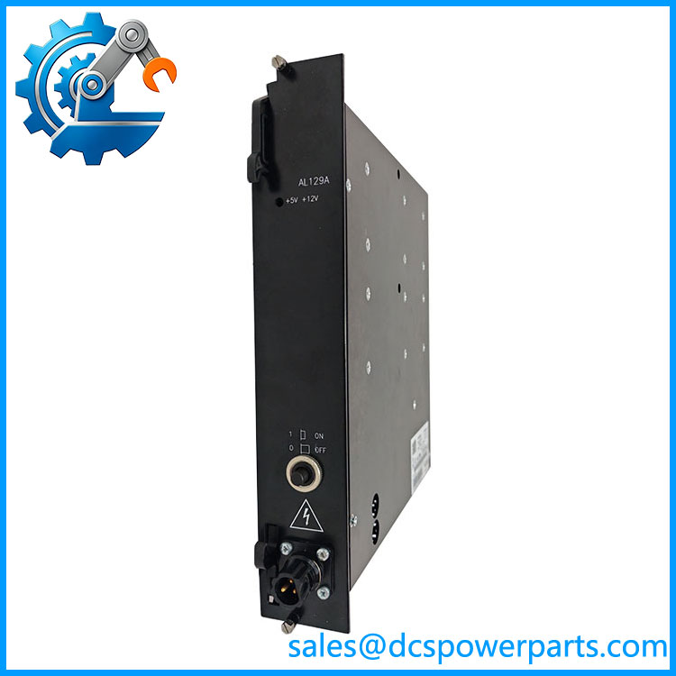
ALSTOMA AL129A
Key Features and Advantages
Wide-range input without a tap change: 96–253 VAC covers a 115 V control feed and a 230 V feed with the same part number, which matters in plants where the auxiliary supply sags to 180 V under a motor start and where a fixed-tap supply would drop the rack.
Active PFC front end, not a plain rectifier: the board rectifies to a regulated intermediate bus near 380 V before the output converters, so the input current is drawn smoothly rather than in narrow pulses. On a control cabinet sharing a board with contactor coils and relay logic, that is the difference between a supply that rides through switching noise and one that transfers it to the logic rails.
Outputs trimmed with headroom: the +5 V rail sits at 5.70 V unloaded and still delivers 5.43 V at 10 A. That deliberate offset absorbs backplane and connector drop, so cards at the far end of FB178 see a rail inside tolerance instead of a marginal one — a detail that explains why a replacement reading exactly 5.00 V unloaded should be checked rather than admired.
Current-limited trip with automatic recovery: the tested unit cuts out at about 12.8 A on the 5 V rail and 5.5 A on the 12 V rail, extinguishes its output LED and restores itself when the overload clears, without damage to the board. A shorted card or a jammed relay driver therefore costs a reset, not a power supply.
Real redundancy, verified at rack level: the module is designed for single or redundant operation on the FB178 backplane, and the rack raises a power-supply redundancy fault when one of the two is switched off. Two AL129A units and that alarm are the whole availability strategy of an ALSPA CE2000 cabinet, and the alarm is the only thing that tells you the second unit has quietly died.
Cassette mechanics that suit a live cabinet: 5 cm pitch, extractor handle, front-mounted switch, fuses F1 and F2 at 3.15 A time-lag. The unit can be pulled and refitted without disturbing the backplane wiring of neighbouring cards, and the front switch lets a redundant unit be isolated for test without opening the cabinet.
Three identifiers on one label: AL129A, CD101152 with a revision letter, and Alstom code U0100050. Record all three in the plant file; a quotation that offers the right product code with the wrong Alstom code is a quotation for a different generation of the same cassette.
Honest thermal behaviour: roughly 64 °C internal hot-spot unloaded and 71.5 °C at full 5 V load, convection cooled, in a 265 mm square cassette. That is a component-life number to design around — cabinet ventilation and filter condition matter more to this module’s service life than any specification on the label.
Applications
Steam and gas turbine control cabinets: the ALSPA CE2000 platform was Alstom’s turbine control and sequencing system, and is the supply inside those racks — governor, sequencer, protection and I/O cards all drawing from the two rails it generates. On a unit that is still running, this module is the one spare that decides whether a night-shift trip becomes a two-hour outage.
Combined-cycle and cogeneration plant control: auxiliary control, burner management and balance-of-plant cabinets built on the same racks, where the AC feed comes from a UPS but the local distribution still sags when large drives start.
Hydro unit control and plant automation: governor and unit-sequence cabinets in older hydro stations, frequently fed at 115 V or 220 V depending on the station’s vintage — the wide input range means one spare covers both.
Industrial plants that inherited Alstom drive and control packages: cement lines, paper mills and metals plants that bought Alstom drives together with an ALSPA control system, now maintaining a mixed cabinet estate where the drives are still supported but the control platform is not.
Rail and infrastructure control rooms: not because the module is a “rail transit control module”, but because Alstom supplied signalling and traction auxiliary control systems built on the same racks; the power supply in those cabinets is the same cassette.
Obsolescence-driven reverse engineering: plants cataloguing a legacy cabinet before migration, where photographing the nameplate of — including CD101152, the revision letter and U0100050 — is the only way to specify a like-for-like replacement before the last unit fails.
Related Products
AL132A (U0100500) — the DC-input sister of the same cassette: 24–48 VDC in, identical +5 V/10 A and +12 V/4 A outputs, same AM163/AM164/AM166 racks and FB178 backplane; use it where the cabinet feed is a DC battery system rather than AC. AM163 — CE2000 rack accepting the integrated power supply in single or redundant configuration. AM164 — larger rack of the same family, same power-supply cassette and backplane interface. AM166 — rack variant used where additional card positions are required; power supply fitment unchanged. FB178 — the backplane that carries the supply outputs and the rack’s redundancy-fault detection; the connector condition here decides whether a good module actually powers the rack. CE3000 — the later Alstom controller family that shares the same power-supply cassettes, so an spare can serve both generations. ALSPA P320 — the successor platform family in the same Alstom control lineage; the migration target when a cabinet reaches end of support.
Installation and Maintenance
Before installation: confirm the cabinet feed is single-phase 96–253 VAC, 50 Hz, that fuses F1 and F2 are 3.15 A time-lag, and that the rack position is the power-supply slot on an AM163, AM164 or AM166 rack with a sound backplane connector. Read the label and record all three identifiers — , CD101152 with revision letter, U0100050 — because a replacement of the wrong revision may fit mechanically and still differ in detail. Isolate the incoming feed, verify dead, and only then withdraw the cassette by its extractor handle; never pull a unit that is the sole supply on a live rack, and never work on one with the front switch on.
Commissioning: insert the cassette until the backplane engages, restore the feed, and check the +5V and +12V LEDs before loading the rack. Measure both rails at the backplane with the rack fully populated — expect the unloaded +5 V to read high, in the region of 5.7 V, and to fall toward 5.4 V at full load; a rail that reads low unloaded points to a tired output stage, not to a healthy margin. On a redundant pair, prove the arrangement the way a test bench does: switch one unit off, confirm the rack stays powered and that a redundancy fault is annunciated, then restore it and confirm the alarm clears.
Maintenance: the wear items are electrolytic capacitors in the PFC and flyback stages, the two input fuses, and dust on the convection surfaces. Inspect annually for bulged capacitors, discoloured heatsinks, fan-free airflow obstruction and loose front connectors; compare the loaded output voltages against the values recorded at commissioning rather than against the label. A slowly falling loaded +5 V rail is the earliest warning of end of life, and a unit that trips below its rated current is already there. Keep one tested spare per critical rack, exercise the redundancy test at every outage, and treat the hot-spot figure of roughly 71 °C at full load as the reason cabinet filters are not optional.
Warranty and Quality
Every is supplied as the ALSPA integrated power supply it actually is — CD101152 with its revision letter and Alstom code U0100050, 96–253 VAC in, isolated +5 V/10 A and +12 V/4 A out, for AM163/AM164/AM166 racks on the backplane — never as the “rail transit module”, “vibration card” or “SIL 3 relay module” that uncritical listings describe. Units are identified by nameplate in photographs before dispatch, so the buyer sees the product code, the OEM part number, the revision and the Alstom code that will actually arrive. Each module is power-tested with a variable AC source, both rails measured unloaded and at rated load, overload trip and automatic recovery verified, input fuses confirmed as 3.15 A time-lag, and the internal hot-spot checked by thermal imaging; where a test bench is available, detection on the rack bus and redundancy-fault annunciation are proven as well. A 12-month repair, replacement or refund commitment applies. Technical support covers the questions this part really raises: how , and relate, which revision suits which rack, why the unloaded +5 V rail reads high by design, how to prove redundancy without dropping the cabinet, and how to plan a spare against a platform that will not be manufactured again.
免费
今天 10:14