Description
Product Overview
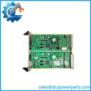
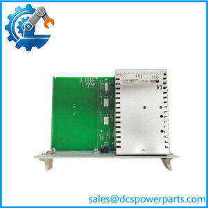
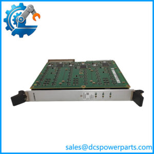
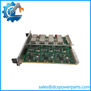
The ALSTOM NRD108028 8RDB43655 SA43655.E is a legacy ALSTOM control/interface board associated with the NRD108028 identification. Available product references consistently group NRD108028, 8RDB43655, and SA43655.E as the same ALSTOM hardware family. Its functional description varies between “control module,” “safety control module,” and relay-output board, so the exact application should be established from the host cabinet documentation rather than relying on a generic product title.
From an engineering standpoint, the ALSTOM NRD108028 belongs on the interface side of a control/protection system. Available technical information describes an eight-channel relay-output arrangement, with the relay contacts used for functions such as alarms, permissives, breaker commands, and other discrete control actions. The board communicates with the host controller through a proprietary backplane rather than presenting itself as a conventional standalone PLC I/O module.
The ALSTOM SA43655.E identification is particularly useful when matching physical spares because 8RDB43655 and SA43655.E appear alongside NRD108028 in multiple ALSTOM product indexes. One source claims a 12 VDC input and 24 VDC/10 A output arrangement, while another describes an 8-channel relay board with up to 2 A at 30 VDC. These specifications conflict and should not be treated as guaranteed ratings. For a plant-critical replacement, the original wiring diagram and board markings should take precedence.
Key Technical Specifications
| Parameter | Value |
|---|---|
| Manufacturer | ALSTOM |
| Primary Model | |
| Board Number | 8RDB43655 |
| Functional Identification | SA43655.E |
| Product Type | Safety Control / Relay Interface Module |
| Primary Function | Discrete relay-output interfacing |
| Reported Channel Count | 8 relay outputs |
| Relay Configuration | SPDT / Form C reported by secondary source |
| Reported Contact Rating | Up to 2 A @ 30 VDC, subject to verification |
| Host Interface | Proprietary backplane |
| Front Communication Port | Not identified |
| Installation | Rack-mounted plug-in board |
| Supply Architecture | Host/backplane dependent |
| Output Voltage | Application dependent |
| Isolation | Relay isolation; exact design requires verification |
| Operating Temperature | Not reliably confirmed |
| Dimensions | Approximately 100 × 160 × 20 mm reported by secondary source |
| Firmware | System dependent |
| Condition | New Surplus, subject to inspection and functional testing |
The eight-relay-output description is supported by a secondary technical listing, but the same source explicitly notes that contact ratings and dimensions should be confirmed against the exact panel drawings and host IED documentation.
Important: Another listing gives 12 VDC input, 24 VDC output, and 10 A output current. That description is inconsistent with the relay-board specification above and should not be used as a confirmed electrical specification.
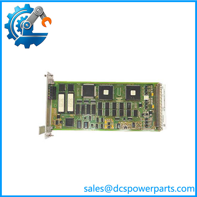
NRD108028
Related Products
- ALSTOM NRD108031 / TRVC070999000 / BOTTOM — Related ALSTOM control module from the same NRD product grouping. Its functional role differs from the relay interface.
- ALSTOM NRD108033 / 8RDC44667G01 / SA44667.C — Related control module in the same product family. It should be treated as a different board unless the host documentation specifically approves substitution.
- ALSTOM NRD108034 / 8RDB44674G01 / SA44674.C — Another NRD-series control module. Its different board number indicates that it should not automatically be treated as an equivalent replacement.
- ALSTOM NRD109475 / 8RDA44670G01 / SA44670.E — Related ALSTOM control module. It shares the NRD family but has a different hardware identification and functional application.
- ALSTOM N895609510K / N895609010R / E32OUT / N895609100P — Digital-output module from another ALSTOM architecture. It provides discrete output functions but is not a drop-in replacement for .
- ALSTOM N897066510E / N897066010M / AOVD / N897066000A — Analog-output module. It handles continuous analog signals, unlike the relay-based discrete interface associated with .
- ALSTOM N897093511D / N897093051D / DIAGNOSTICA / N897093400H — Diagnostic module used for monitoring and fault information rather than relay output control.
- ALSTOM N897163510Q / N897163050Q / MODEM / N897163100U — Communication/modem assembly. Its function is data communications rather than field relay control.
Frequently Asked Questions
1. What is ALSTOM 8RDB43655 .E used for?
Available sources identify it as an ALSTOM control/safety module, with one detailed listing describing it as an 8-channel relay-output board.
Typical applications for this type of interface include:
- Alarm annunciation
- Permissive signals
- Breaker commands
- Discrete control commands
- Status/control interfacing
The actual field assignment depends on the host system.
2. Is a power supply module?
I would not classify it as a power supply based on the strongest available identification.
One secondary listing incorrectly or ambiguously assigns 12 VDC input and 24 VDC/10 A output specifications. Another source explicitly identifies the hardware as an eight-channel relay-output board.
For procurement, the / 8RDB43655 / .E identification should be treated as the primary evidence.
3. How many relay outputs does 8RDB43655 have?
An available technical listing describes eight relay outputs, configured as SPDT/Form C contacts.
That source reports a typical rating of up to 2 A at 30 VDC, but this should be verified against the actual board revision and project wiring documentation before switching a field load.
4. Can I hot-swap the ?
Do not assume hot-swap capability.
Relay outputs may be connected directly to breakers, contactors, permissives, alarms, or other process-control circuits. Removing the board while energized could change output states or interrupt a critical control path.
Unless the applicable ALSTOM documentation explicitly permits energized replacement, use the approved shutdown/isolation procedure.
5. Can I replace with NRD108034 or NRD108033?
Not without documented compatibility.
Although NRD108033, NRD108034, and appear in the same ALSTOM product grouping, they have different board identifiers and therefore should be considered different hardware until the system drawings establish equivalence.
Check:
- Board revision
- Connector pinout
- Rack position
- I/O assignment
- Relay contact configuration
- Field voltage/current
- Host firmware
- Application configuration
6. Will replacing erase my PLC/DCS logic?
The board is identified primarily as a control/interface module rather than the main application CPU. Therefore, the central control logic would normally reside elsewhere.
The replacement risk is instead concentrated around I/O mapping, relay behavior, configuration, and field wiring. Before removal, document every terminal assignment and verify the replacement’s output state behavior.
7. How should I verify a New Surplus before installation?
For a plant-critical spare, I would verify the complete identification:
→ 8RDB43655 → .E
Then inspect:
- PCB and revision markings
- Backplane connector
- Relay condition
- Terminal/interface condition
- Signs of corrosion or storage damage
- Jumper or configuration settings
- Channel assignment
- Relay contact operation
- Insulation/isolation where applicable
- Controlled power-up
- Host communication
- Channel-by-channel functional testing
Procurement judgment: The most defensible identification is ALSTOM / 8RDB43655 / .E, a legacy control/interface module associated with relay-output functionality. Public listings contain conflicting electrical specifications, so I would not publish 12 VDC, 24 VDC/10 A, or other absolute ratings as guaranteed values without the original ALSTOM drawing. For replacement purchasing, the exact part-number chain and field wiring compatibility should be the acceptance criteria.