Description
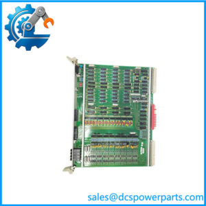
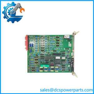
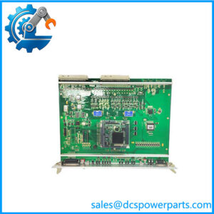
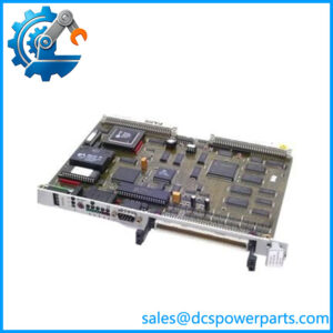
Alstom ICP232 029.359 325 Integrated Controller and Power Interface Board
Product Introduction
A static frequency converter does not tolerate a control board that merely looks electrically similar to the original. Timing, pulse generation, feedback acquisition, and protection logic all sit close to the power-conversion stage. The Alstom ICP232 029.359 325 is documented as an Integrated Controller and Power Interface Board used within the control architecture of a static frequency converter. Its processor handles converter-near control functions, current control, pulse generation, and important protection functions for the mains and machine converters.
The board works alongside the SPU232 processor/controller rather than replacing the entire converter-control system. Documentation identifies 12 analog inputs, 6 binary inputs, 18 binary pulse-feedback inputs, 6 binary outputs, and 4 analog outputs for converter control and monitoring functions. Procurement references also identify the exact 029.359 325 identification number as an Alstom/Converteam control board, so revision and application matching are critical when sourcing a replacement.
Key Technical Specifications
| Parameter | Specification |
|---|---|
| Product Model | ICP232 |
| Identification Number | 029.359 325 |
| Manufacturer / Legacy Brand | Alstom / Converteam |
| Product Type | Integrated Controller and Power Interface Board |
| Primary Application | Static Frequency Converter control |
| Processor Frequency | 225 MHz |
| Supply Reference | 5 VDC / 15 VDC / 24 VDC |
| Analog Inputs | 12 |
| Binary Inputs | 6 |
| Pulse Feedback Inputs | 18 binary inputs |
| Binary Outputs | 6 |
| Analog Outputs | 4 |
| Main Control Functions | Current control, pulse generation, converter-near control, protection |
| Associated Controller | SPU232.1-CAN / SPU232.2 |
| Converter Application | Mains and machine converters |
| Board Architecture | Converter control / power-interface electronics |
The I/O counts and functional role above come from technical documentation for the static frequency converter control system. The 225 MHz and 5/15/24 VDC descriptions are corroborated by procurement and secondary product references, but detailed electrical characteristics for every individual I/O channel should be taken from the converter-specific documentation rather than inferred from the board designation.
Major Features and Advantages
Integrated Converter-Near Control
The ICP232 was designed for control functions physically and functionally close to the power-conversion process. The technical documentation identifies it as a fast processor board integrating the current controller, pulse generator for three 6-pulse converter bridges, converter-near controller, and important protection functions. This is considerably more specific than calling it a generic industrial CPU.
That distinction matters during replacement. A general-purpose VME controller may have comparable processing capability and still be unsuitable because the ICP232’s firmware, timing behavior, pulse interfaces, feedback signals, and converter-specific control logic are part of the overall design.
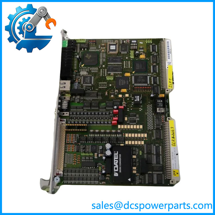
ICP232–029.359-325
Pulse Generation for Converter Bridges
One of the board’s principal functions is generation of the control signals used by the converter pulse-output stages. The associated documentation describes pulse generation for three 6-pulse converter bridges. The pulse output stages then convert the firing-range signals into DC24V pulse sequences for driving the pulse transformers in the power modules.
For a maintenance engineer, this is an important architectural detail. The ICP232 should not be treated as though it directly replaces the downstream pulse-output hardware. It is part of a larger control chain.
Extensive Feedback Acquisition
The board incorporates 12 analog inputs, 6 binary inputs, and 18 binary pulse-feedback inputs. These channels are intended for important converter-near parameters, binary signals, and pulse feedback rather than ordinary plant I/O.
This arrangement allows the converter controller to monitor electrical and operating conditions while executing the control algorithm. When troubleshooting a converter, loss of pulse feedback or incorrect analog feedback can therefore produce symptoms that appear to be power-stage failures even when the problem is actually in the control electronics or signal interface.
Dedicated Outputs for Fast Control Functions
The provides six binary outputs and four analog outputs. The technical documentation specifically notes the analog outputs as being available for display-related or quick control functions.
This makes the board a mixed control/interface device rather than a simple processor carrier. Its replacement should be evaluated as a complete functional assembly, including the connected pulse stages and feedback circuits.
Works Within an SPU232-Based Architecture
The static frequency converter documentation identifies the SPU232.1-CAN or SPU232.2 as the processor board responsible for the broader excitation-equipment, static-frequency-converter, setpoint, and speed-control software functions. The then performs the converter-near functions.
That architecture is worth preserving during modernization. Replacing without confirming the associated type, firmware, converter configuration, and pulse hardware can create a technically incompatible combination even if the replacement board has the same identification number.
Application Scenarios & Field Pain Points
- Static Frequency Converter Systems: is used as part of the control hardware for static frequency converter systems, particularly where fast converter-near control and pulse generation are required.
- Mains Converter Control: The board contributes current-control and protection functions associated with mains-side converter operation.
- Machine Converter Control: The same hardware architecture supports control and protection functions on the machine-converter side.
- Legacy Alstom / Converteam Equipment: Procurement documentation identifies 5/15/24VDC, 225 MHz, Ident-No. 029.359 325 as an Alstom/Converteam control board.
Field note: The biggest sourcing risk is confusing the with the . They are different boards with different responsibilities. The provides the broader converter-control software functions, while the handles converter-near control, pulse generation, feedback, and protection.
Related Products
- .1-CAN 029.354 630 — processor board associated with the static frequency converter control architecture.
- .2 029.366 817 — alternative processor-board identification documented with the .
- VME-PROF-S 029.363 054 — another board identified within the same broader Alstom control hardware family in current certification documentation.
- Pulse Output Stage 029.151 150 — downstream interface hardware that converts firing-range signals to DC24V pulse sequences for the power modules.
- 029.359 325/07 — an alternative designation reported in secondary documentation; verify the actual board revision before treating it as an interchangeable variant.
Do not assume that these related boards are direct substitutes. Their positions in the converter-control architecture are different.
Engineer’s Guide: Field Pitfalls to Avoid
1. Do not confuse with
The two boards perform different jobs. provides the broader control software functions, while performs converter-near control and interfaces with the pulse-generation architecture.
2. Match the complete identification number
Use / 029.359 325 as the primary procurement reference. A similar-looking board number or an alternative revision should not be accepted simply because the PCB dimensions appear identical.
3. Verify the converter application
The is tied to a specific static-frequency-converter control architecture. Confirm the converter model, associated board, pulse stages, firmware, and system configuration before installing a replacement.
4. Do not treat the I/O as ordinary PLC I/O
The 12 analog inputs, binary inputs, pulse-feedback inputs, outputs, and analog outputs serve converter-control functions. Their electrical characteristics and signal conditioning should be checked against the original converter documentation before wiring changes are attempted.
5. Protect the board during handling
This is processor-level electronics connected to converter control circuitry. ESD precautions, controlled power-down procedures, correct connector orientation, and verification of the associated power rails should be part of the replacement procedure.
6. Confirm firmware and parameter compatibility
A physically correct does not automatically guarantee a working converter. The control board operates within a larger software and parameter set. Capture existing configuration information before removing the original board whenever the system permits it.
FAQ
What is Alstom 029.359 325?
It is an Integrated Controller and Power Interface Board used in a static frequency converter control system. Its documented functions include current control, pulse generation, converter-near control, and protection for mains and machine converters.
Is a PLC module?
No. Although it performs processor and I/O functions, it is specialized converter-control hardware rather than a general-purpose PLC I/O module. Its signal interfaces and firmware are tied to the static frequency converter architecture.
What is the difference between and ?
The acts as the higher-level processor board for the static frequency converter and related control functions. The is the converter-near controller/interface board handling current control, pulse generation, feedback, and protection functions.
How many inputs and outputs does the have?
The referenced technical documentation specifies 12 analog inputs, 6 binary inputs, 18 binary pulse-feedback inputs, 6 binary outputs, and 4 analog outputs. These should not be interpreted as conventional PLC channels because they serve dedicated converter-control functions.
What power supply is associated with 029.359 325?
Procurement references identify the board as 5/15/24VDC, while secondary product documentation also lists those supply rails. The exact rail requirements and allowable tolerances should be confirmed against the equipment-specific electrical documentation before energizing a replacement.
Is 029.359 325 still used in industrial equipment?
The part is associated with legacy Alstom/Converteam static-frequency-converter equipment. A 2025 conformity declaration still identifies 029.359 325 under the Alstom trademark, but that does not establish current factory production or standard availability.
What should procurement verify when buying a replacement?
Match , identification number 029.359 325, the PCB revision, connector arrangement, associated processor, converter type, firmware/configuration, and pulse-output-stage arrangement. For used inventory, verify the actual board marking and physical condition rather than relying only on a seller’s description.
Procurement Takeaway
029.359 325 is specialized Alstom/Converteam static-frequency-converter control hardware. The available technical documentation gives it a much more specific role than the generic descriptions often found in surplus listings: it is the Integrated Controller and Power Interface Board responsible for converter-near current control, pulse generation, feedback processing, and protection functions.
For a replacement, the correct approach is to match the complete / 029.359 325 identification and then verify the surrounding , pulse-output hardware, firmware, and converter configuration. Treating it as a generic control board is the wrong procurement strategy.