Description
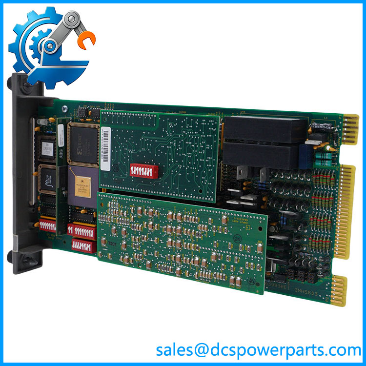
ABB Bailey IMHSS03-MA Hydraulic Servo Module
Product Introduction
Turbine valve control is one of the places where a generic analog output module is simply not an adequate substitute. The ABB Bailey IMHSS03-MA is identified as the redundant Hydraulic Servo Module for the INFI 90 control platform, providing the interface between the control processor and a hydraulic actuator through a servo valve or I/H converter. LVDT feedback gives the controller the actuator-position information required for closed-loop positioning. ABB documentation identifies this HSS architecture for steam-turbine throttle and control valves, gas-turbine fuel valves, inlet guide vanes, and nozzle-angle applications.
The underlying IMHSS03 design includes redundant servo-valve outputs, LVDT excitation and feedback circuits, manual raise/lower inputs, trip-bias handling, and an isolated hard-manual output. The module communicates with an INFI 90 multi-function processor through the I/O expander bus and is accessed through function code 55 or 150. For the -MA redundant configuration, procurement should preserve the installed servo topology, LVDT arrangement, termination hardware, and controller configuration rather than treating the suffix as a cosmetic ordering detail.
Key Technical Specifications
| Parameter | Specification |
|---|---|
| Product Model | IMHSS03-MA |
| Manufacturer | ABB Bailey |
| System Family | INFI 90 / Harmony Rack |
| Product Type | Redundant Hydraulic Servo Module |
| Primary Function | Hydraulic actuator valve-position control |
| Controller Interface | INFI 90 I/O Expander Bus |
| Compatible Controller Family | IMMFP01 / IMMFP02 / IMMFP03 |
| Function Codes | FC55 / FC150 |
| Position Feedback | LVDT |
| LVDT Secondary Inputs | 4 analog inputs total; 2 secondary inputs per LVDT |
| LVDT Input | 24 Vpp, ±7 VDC common mode, 10 kΩ differential impedance |
| LVDT Excitation | 400 Hz to 15 kHz; configurable amplitude |
| Servo Valve Outputs | 2 redundant selectable analog outputs |
| Servo Output Range | ±8 to ±64 mA, selectable |
| Maximum Coil Impedance | 750 Ω at ±8 mA down to 93 Ω at ±64 mA |
| I/H Converter Output | 4–20 mA into 300 Ω or 20–160 mA into 15 Ω |
| Position Meter Output | 4–20 mA into 300 Ω |
| Unscaled Feedback Output | 2 mA into minimum 5 kΩ |
| Digital Inputs | Raise, lower, and trip bias |
| Digital Input Isolation | Optically isolated, 250 VDC |
| Hard-Manual Output | Optically isolated open-collector |
| Module Supply | +5, +15, -15, and +24 VDC from system/termination hardware |
| +5 VDC Consumption | 576 mA nominal / 940 mA maximum |
| +15 VDC Consumption | 15 mA nominal / 27 mA maximum |
| -15 VDC Consumption | 12 mA nominal / 18 mA maximum |
| +24 VDC Consumption | 335 mA nominal / 570 mA maximum |
| Operating Temperature | 0 to 70°C |
| Humidity | 5–90% RH to 55°C, noncondensing |
| Mounting | One slot in INFI 90 MMU |
| Status Indication | Nine front-panel LEDs |
The electrical values above come from the original Bailey IMHSS03 technical instruction. In particular, the servo output capability depends on the selected current range and corresponding coil impedance; it is not correct to quote one generic servo-current rating for every installation.
Application Scenarios & Pain Points
1. Steam-turbine throttle and governor valves
The HSS module receives a position demand from the multi-function processor and converts that demand into servo-valve control. The hydraulic actuator then moves the turbine valve to the required position.
2. Gas-turbine fuel valve control
The same control architecture can be used for gas-turbine fuel-valve positioning. The HSS module closes the loop using LVDT feedback rather than relying only on the commanded position.
IMHSS03-MA
3. Redundant servo-valve arrangements
The IMHSS03 design supports two servo outputs that can be configured for two active controlling valves or for one active valve with another in standby. That redundancy is a major reason the exact module/configuration matters in turbine-control applications.
4. I/H converter applications
The HSS can interface with an I/H converter using either a 4–20 mA or 20–160 mA output arrangement, depending on configuration. The connected actuator and converter specifications must determine which mode is appropriate.
5. Manual control during processor communication loss
The module includes raise/lower contact inputs and a trip-bias circuit. Bailey documentation describes a hard-manual function that allows actuator control when communication with the MFP is lost or the processor enters a configuration condition.
Related Products
- ABB Bailey IMHSS03 — standard Hydraulic Servo Module; the technical documentation provides the core electrical and functional specifications for the HSS03 design.
- ABB Bailey IMHSS01 / IMHSS02 — earlier HSS modules that was designed to replace.
- ABB Bailey SPHSS13 — later Symphony Plus HSS module identified by ABB as a direct replacement path for and several related HSS modules. ABB documents support for AC/DC LVDTs and servo output capability up to 300 mA on SPHSS13.
- ABB Bailey IMMFP01 — Multi-Function Processor used with the HSS control loop.
- ABB Bailey IMMFP02 — later MFP variant used in INFI 90 architectures.
- ABB Bailey IMMFP03 — another compatible MFP family member documented with .
- ABB Bailey IMFCS01 — Frequency Counter Module commonly used with the MFP/HSS turbine-control arrangement for turbine-speed measurement.
- ABB Bailey NTHS03 — Hydraulic Servo Termination Unit associated with .
- ABB Bailey NKHS03 — termination cable used between NTHS03 and .
Engineer’s Guide — Field Pitfalls to Avoid
1. Do not substitute a standard HSS03 without checking redundancy
The IMHSS03-MA is specifically identified in procurement references as a redundant Hydraulic Servo Module. The servo arrangement—two active outputs versus primary/standby—has to match the existing turbine-control design.
2. Record the LVDT configuration before removing the old module
The HSS module supports redundant LVDT feedback and configurable excitation. The original manual documents selectable excitation frequency from 400 Hz to 15 kHz and configurable excitation amplitude. Copy the existing configuration rather than assuming the replacement can be inserted with factory defaults.
3. Match the servo-coil current range to the actual valve hardware
The documented servo outputs range from ±8 mA through ±64 mA, with the permissible coil impedance changing accordingly. A current setting suitable for one servo valve may be wrong for another.
4. Check the termination unit and cable
The HSS module does not put all field wiring directly on the PCB. Bailey documentation identifies the NTHS03 Hydraulic Servo Termination Unit and NKHS03 termination cable as associated hardware. Verify both before declaring a replacement compatible.
5. Do not overlook the trip-bias circuit
Trip bias is not an ordinary digital command. The original documentation states that activating the trip-bias input drives the actuator toward the zero-percent/fully closed position for shutdown. That makes wiring verification particularly important during turbine-control maintenance.
6. Preserve function-code configuration
The MFP uses function code 55 or 150 to configure and access the HSS module. Module address, operating mode, calibration information, LVDT configuration, and control parameters are part of the system configuration—not simply properties of the physical card.
7. Treat removal as a control-loop intervention
Bailey explicitly warns that installing, removing, or adjusting the module can upset the controlled process. The original instruction also identifies the PCB as containing electrostatic-sensitive devices. Replacement work belongs in an approved maintenance procedure with the turbine/control loop secured as required.
FAQ
What is the ABB Bailey -MA?
The -MA is a redundant Hydraulic Servo Module associated with the ABB Bailey INFI 90/Harmony control architecture. It provides valve-position control between an INFI 90 processor and hydraulic actuators through servo valves or I/H converters.
Whathe control?
Typical applications include steam-turbine throttle and governor valves, gas-turbine fuel valves, inlet guide vanes, and nozzle-angle mechanisms. The module uses LVDT feedback to determine actuator position.
es support redundant servo valves?
Yes. The architecture provides two redundant selectable servo outputs. Bailey describes configurations with both servo valves active or one active with the other in standby.
What LVDT signals does the HSS03 support?
The module provides two LVDT primary excitation outputs and four analog secondary inputs, with two secondaries associated with each LVDT. Excitation frequency is configurable from 400 Hz to 15 kHz; the documentation also describes support for DC LVDT operation.
What is the servo output range?
The documented selectable servo-valve output ranges are ±8, ±16, ±24, ±32, ±40, ±48, ±56, and ±64 mA. The corresponding maximum coil impedance ranges from 750 Ω at ±8 mA to 93 Ω at ±64 mA.
Can it control an I/H converter?
Yes. The HSS module provides an I/H converter output that can be configured for 4–20 mA into 300 Ω maximum or 20–160 mA into 15 Ω maximum, depending on the application configuration.
What controller is normally associated with ?
The original Bailey documentation identifies IMMFP01, IMMFP02, and IMMFP03 Multi-Function Processor Modules as compatible processors. Function code 55 or 150 is used to configure and access the HSS module.
Is SPHSS13 a replacor ?
ABB identifies SPHSS13 as a direct replacement for and related HSS modules in its Symphony Plus lifecycle documentation. That does not mean everyng installation can be changed without engineering work: the LVDT type, redundancy arrangement, termination hardware, servo-coil configuration, and controller configuration should still be checked.
What should procurement verify befong ?
Verify the exact designation, hardware revision, redundant configuration, LVDT arrangement, servo-valve current requirements, termination unit, cable, and existing MFP/function-code configuration. For surplus or refurbished stock, the published specifications describe the design; they do not establish the condition of a particular board.