Description
Product Overview
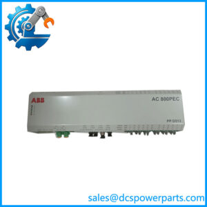
Distributed control systems often need to collect signals from equipment located outside the main controller cabinet. The ABB ICMK14N1-I10.0 is associated with ABB’s Advant Controller 31 (AC31) automation platform and serves as a remote I/O unit for field signal acquisition and output control. It connects field devices to a compatible control architecture, allowing digital input states to be monitored and output commands to be transmitted without routing every field signal directly to the central controller. This arrangement is useful in machinery, process equipment, and distributed automation installations where localized I/O reduces wiring runs and simplifies cabinet organization.
The documented ICMK14N1 hardware provides eight 24 V DC digital inputs and six 24 V DC transistor outputs. The output channels have different current ratings: outputs 0 and 1 are rated up to 1 A each, while outputs 2 through 5 are rated up to 0.5 A each, according to the available product information. The unit supports Modbus communication, with automatic baud-rate detection documented across 1,200 to 187,500 baud. These features allow compatible controllers to read input states and command connected loads, subject to the module’s electrical limits and configured communications.
For an AC31 system replacement or maintenance project, verify the exact hardware suffix, supply arrangement, Modbus settings, and output wiring before installing the ICMK14N1-I10.0. ABB’s technical documentation also identifies the ICMK14N1-M family, so the complete model designation should be reconciled with the physical nameplate rather than assumed to be interchangeable across every suffix. Check whether external power or extension modules are present, confirm output load compatibility, and validate communications with the intended master. Since this is an established control-system platform, preserving the existing configuration and testing every channel before returning the machine to service are essential.
Product Introduction (Non-Templated)
A remote I/O fault can stop a machine even when the central controller is still running. The ABB ICMK14N1-I10.0 is associated with the AC31 platform and provides eight 24 V DC inputs and six transistor outputs for distributed signal handling.
Its documented Modbus interface automatically detects baud rates from 1,200 to 187,500 baud. For a legacy replacement, confirm the complete order code, communication settings, and load current of each output before commissioning.
Key Technical Specifications
| Parameter | Value |
|---|---|
| Product Model | ICMK14N1-I10.0 |
| Order Number | 1SBP260052R1001 |
| Manufacturer | ABB |
| Product Series | Advant Controller 31 (AC31) |
| Product Type | Remote I/O unit |
| Digital Inputs | 8 |
| Digital Input Rating | 24 V DC |
| Digital Input Current | Approximately 5–6 mA, depending on documented input conditions |
| Digital Outputs | 6 transistor outputs |
| Output Voltage | 24 V DC |
| Outputs 0–1 | Up to 1 A per output |
| Outputs 2–5 | Up to 0.5 A per output |
| Communication Protocol | Modbus RTU |
| Communication Speed | 1,200–187,500 baud, with automatic detection documented |
| Serial Interface | Confirm the physical interface and wiring from the applicable manual |
| Power Supply | 24 V DC is reported; confirm the supply arrangement and power consumption on the exact hardware |
| Extension Capability | Depends on the AC31 configuration and supported extension modules |
| Mounting | Confirm the mounting arrangement against the installed unit |
| Condition | Unverified |
| Hardware Revision | Requires nameplate verification |
The input/output figures and communication capabilities are based on documentation for the family. Confirm the exact I10.0 suffix, power requirements, and terminal assignments before using this table as a commissioning specification.
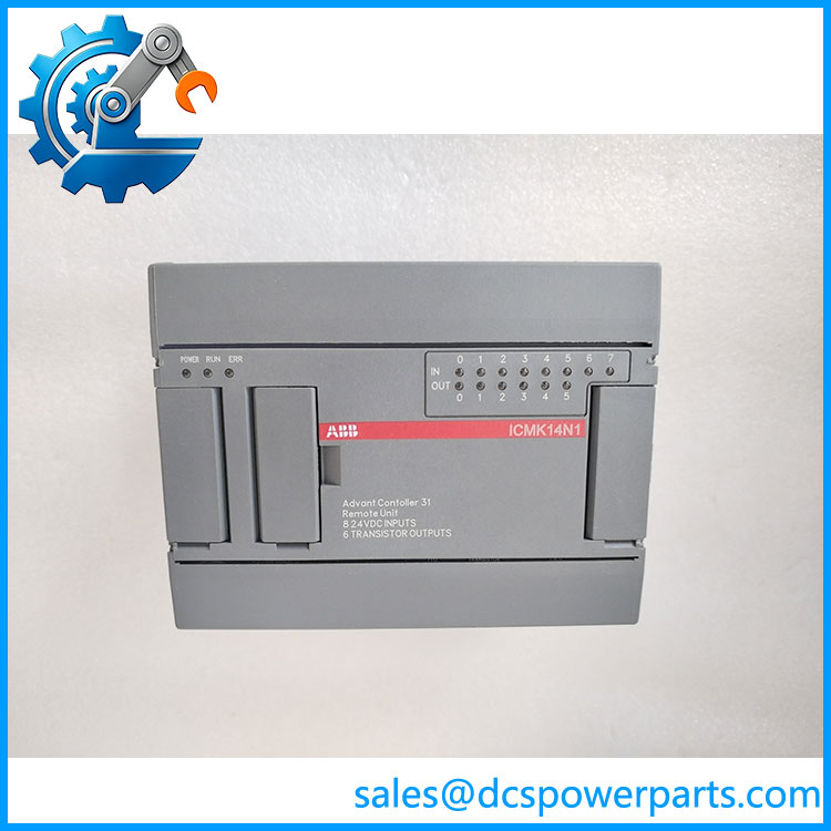
ICMK14N1-I10.0
Related Products
The following products are related to the AC31 platform or the ‘s remote signal-handling role. They are not necessarily direct replacements.
1. -M — A documented family designation. Use the applicable manual to compare suffixes, supply requirements, and terminal assignments before considering it equivalent to the -I10.0.
2. ICMK14F1-M — A related remote unit documented for Modbus master communication. Its role and configuration differ from the variant, so verify the intended network architecture before substitution.
3. ABB Advant Controller 31 () basic unit — The controller platform used with compatible remote I/O equipment. Confirm the supported communication interface and controller configuration before connecting a replacement module.
4. digital I/O extension modules — Compatible extensions can expand signal capacity in supported arrangements. Selection depends on the base unit, extension limits, and required input/output types.
5. analog I/O modules — Used when the application requires analog measurements or control signals rather than the ‘s documented digital I/O. Verify channel count, signal range, resolution, and controller support.
6. 24 V DC power supply — Provides the required DC supply where specified by the installed configuration. Verify current capacity, grounding, protection, and whether the unit requires an external supply for its particular arrangement.
7. Modbus RTU master controller — Communicates with compatible remote units and reads or writes supported registers and coils. Verify supported function codes, baud rate, addressing, and serial wiring.
8. 24 V DC digital sensors and switches — Supply field status signals to the remote unit’s digital inputs. Check input polarity, switching thresholds, and current requirements before wiring.
9. 24 V DC transistor-compatible loads — Actuators, relays, or interface devices may be driven through the module’s outputs when their current requirements and electrical characteristics fall within the channel ratings. Use suitable interposing relays or protection where required.
10. -compatible programming and configuration tools — Required tools depend on the controller and installed software revision. Confirm that the available software can communicate with the existing system before attempting configuration changes.
Frequently Asked Questions (FAQ)
1. Can I replace the existing with -I10.0 without changing the wiring?
Not without checking the full model designation and terminal arrangement.
Before installation:
- Compare the complete ordering codes and nameplates.
- Verify the 24 V DC supply and grounding requirements.
- Check all eight input connections and six output assignments.
- Confirm the output load currents are within their channel ratings.
- Match the Modbus address, baud rate, and communication wiring.
A shared model prefix does not prove that every hardware suffix is interchangeable.
the .0 support firmware version 3.1?
Firmware version 3.1 compatibility has not been established for this exact designation. The relevant controller, remote-unit revision, and configuration software must be identified before planning a software change.
Confirm the approved software version and configuration procedure in the applicable documentation. Do not load firmware intended for another module solely because the model names look similar.
3. Can I hot-swap this remote I/O unit while the machine is running?
Do not assume hot-swapping is supported.
Removing the module may interrupt input monitoring and output control. Depending on the machine’s logic, this could stop a sequence, de-energize an actuator, or cause a communication fault.
Before replacement, determine the system’s response to loss of remote I/O, arrange an approved maintenance window or safe-state procedure, and verify every channel after installation.
4. Will replacing the erase my PLC program?
The remote I/O unit should not be treated as the sole repository for the controller’s application program. However, replacement can still affect I/O mapping, communication configuration, and the operation of connected equipment.
Before removing the unit, back up the controller program and record the remote unit’s Modbus settings and channel assignments. After replacement, verify input states, output behavior, and the controller’s fault diagnostics before resuming normal operation.
5. How can I verify that a lus .0 is authentic and functional?
A new-surplus label alone does not establish authenticity or operating condition.
- Check the model, order number, and serial information on the physical nameplate.
- Inspect the enclosure, terminals, and connectors for damage.
- Confirm the power-supply arrangement and hardware revision.
- Request a test report covering all eight inputs, six transistor outputs, and Modbus communication.
- Verify output operation under an appropriate test load rather than relying only on indicator LEDs.
For an established installation, channel-by-channel testing is preferable to accepting a unit based on appearance alone.
6. What warranty should I expect when purchasing this ABB remote I/O unit?
Warranty coverage depends on the supplier’s written terms and the verified condition of the unit. Do not assume that a legacy or new-surplus module carries the same manufacturer warranty as a newly purchased component.
Before ordering, confirm the warranty period, functional-failure coverage, return conditions, and whether the supplier provides a test report. Record the complete order number on the purchase documentation.
the .0 communicate with a Modbus PLC or DCS?
The family supports Modbus communication, and the technical manual documents automatic baud-rate detection between 1,200 and 187,500 baud. It also lists supported Modbus function codes for reading and writing bits and words.
Before integration, verify the serial interface, bus wiring, address, supported function codes, and register or coil mapping. Test read and write operations with the intended master, then confirm that the returned input states and commanded outputs match the physical I/O.
ProcuremenThe .0 is associated with ABB’s remote I/O platform, with order number 1SBP260052R1001 reported for the . Verify the exact nameplate suffix, supply configuration, and output ratings before purchase or commissioning.