Description
Product Introduction
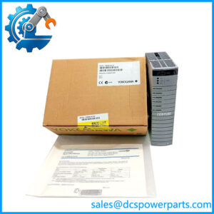
In a legacy process loop, replacing a controller is rarely just a matter of matching the front-panel dimensions. The Yokogawa YS1700-120/A06/A31 combines the YS1700 programmable indicating controller with a YS100-compatible enclosure, an isolated two-wire transmitter input, and RS-485 communications. Yokogawa specifies the YS1700 as a programmable single-loop controller capable of supporting application-specific control functions through its user program.
The Yokogawa YS1700-120/A06/A31 is particularly relevant where an older YS-series controller needs to be retained or replaced without abandoning the existing process architecture. The /A06 option accepts a 4–20 mA signal from a two-wire transmitter and supplies the transmitter, while /A31 provides RS-485 communication supporting PC-link, Modbus, YS protocol, and peer-to-peer communication. Yokogawa’s own replacement documentation specifically shows YS170 configurations being converted to YS1700-120/A06/A31.
Key Technical Specifications
| Parameter | Specification |
|---|---|
| Product Model | YS1700-120/A06/A31 |
| Manufacturer | Yokogawa |
| Product Series | YS1000 |
| Product Type | Programmable indicating controller |
| Controller Function | Single-loop programmable control |
| Use Code | -1, with hard manual unit |
| Type Code | 2, compatible type for YS100 with YS100 case |
| Power Code | 0 |
| Power Supply | 100 VAC / 24 VDC common power |
| Direct Input Option | /A06 |
| Input Type | Isolated two-wire transmitter input |
| Input Signal | 4–20 mA DC |
| Input Resistance | 250 Ω |
| Allowable Input | 40 mA DC |
| Communication Option | /A31 |
| Communication Interface | RS-485 |
| Supported Communication | PC-link, Modbus, YS protocol, peer-to-peer |
| Control Functions | Programmable control functions, including PID applications |
| Configuration Software | YSS1000 setting software |
| Enclosure Compatibility | YS100 |
| Primary Application | Process control and indication |
Yokogawa specifies the /A06 input as a two-wire transmitter input with field isolation, 250 Ω input resistance, and a 4–20 mA DC input signal. The /A31 option provides RS-485 communication and supports PC-link, Modbus, YS protocol, and peer-to-peer communication.
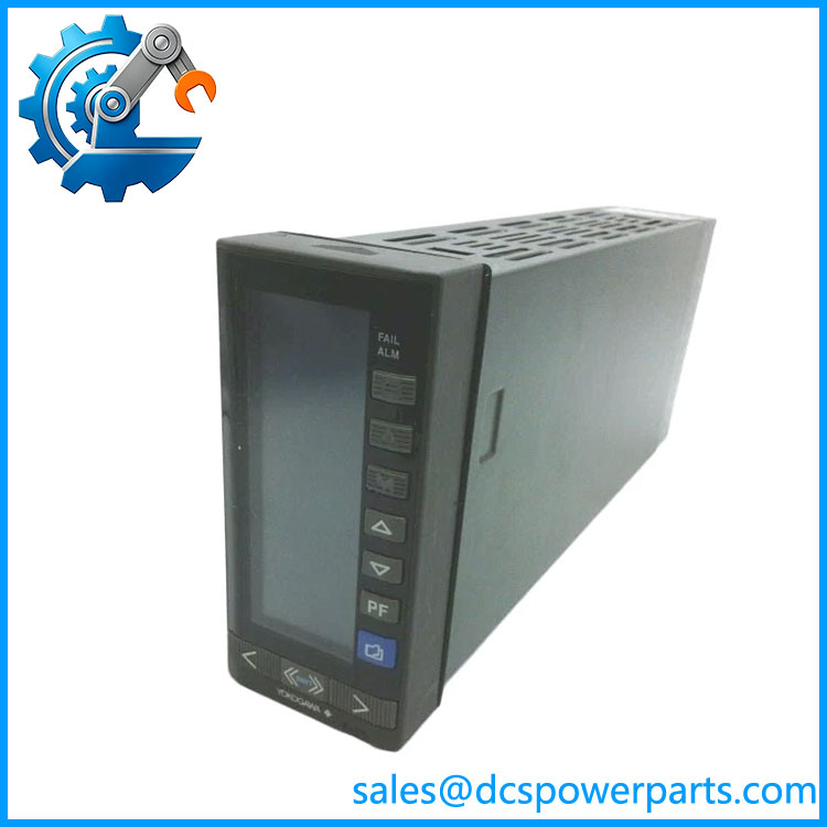
YS1700-120/A06/A31
Application Scenarios & Pain Points
The is useful where a compact controller still has to perform more than simple indication. It can execute programmed control functions while communicating process information to higher-level PLC, SCADA, or DCS equipment.
- Single-loop process control: Suitable for individual temperature, pressure, flow, level, or similar process loops where local control and indication are required.
- 4–20 mA transmitter loops: The /A06 configuration is specifically intended for isolated two-wire transmitter signals.
- PLC and DCS integration: /A31 RS-485 communication supports Modbus and other Yokogawa communication methods, allowing the controller to exchange data with supervisory equipment.
- YS100 replacement projects: The -120 configuration is the YS100-compatible version, and Yokogawa’s replacement guide provides explicit YS-series conversion examples involving /A06 and /A31.
- Legacy control-panel refurbishment: The -compatible case can be useful when maintaining an existing panel arrangement rather than redesigning the complete enclosure.
Field note: When replacing an older YS-series controller, the physical fit is only the first check. The actual engineering work is in recovering the control parameters, transmitter scaling, alarm limits, output behavior, communication mapping, and user program.
Related Products
- Yokogawa YS1700-120 — Base -compatible controller configuration with 100 VAC / 24 VDC common power.
- Yokogawa YS1700-120/A31 — Adds RS-485 communication without the /A06 transmitter-input option.
- — Adds the isolated two-wire transmitter input without /A31 communication.
- Yokogawa -121/A06 — 220 VAC version with /A06 input; power configuration differs from the -120 version.
- — configuration with DCS-LCS communication rather than /A31 RS-485.
- — Ethernet communication configuration using Modbus/TCP on supported configurations.
- Yokogawa YS1500 — Indicating-controller family member intended for applications where programmable control functionality is not the same requirement as the .
- Yokogawa YS170 — Older single-loop programmable controller family that the was designed to replace; Yokogawa provides model-conversion guidance.
These models should not be treated as interchangeable solely because they share the YS1000 family. Input options, communication interfaces, power configuration, enclosure compatibility, and user-program requirements must be checked individually.
Engineer’s Guide — Field Pitfalls to Avoid
1. Verify the complete suffix code
/A06/A31 is a configuration, not merely a model number. Removing /A06 or /A31 changes the controller’s field interface.
Avoidance: Match the complete nameplate designation, including every slash option, before ordering.
2. Do not confuse /A06 with /A07
Both options are for two-wire transmitters, but Yokogawa specifies /A06 as isolated and /A07 as non-isolated.
Avoidance: If the original loop relies on isolation, do not substitute /A07 merely because the signal is also 4–20 mA.
3. Confirm the transmitter loop budget
The /A06 input has a 250 Ω input resistance and supplies the connected two-wire transmitter. Yokogawa gives the external-load relationship in its specifications.
Avoidance: Check transmitter minimum operating voltage, cable resistance, barriers, isolators, and other loop devices before commissioning.
4. Check RS-485 parameters and protocol
The /A31 option supports multiple communication methods, including Modbus and PC-link.
Avoidance: Record station address, communication speed, protocol, wiring polarity, termination, and PLC/DCS register mapping before removing the original controller.
5. Recover the user program before replacement
The is a programmable controller, not simply a fixed-function indicator. Yokogawa provides YSS1000 setting software for configuring the .
Avoidance: Back up the existing user program and parameters whenever possible. Do not assume that a replacement unit will contain the same application logic.
6. Check the -120 power configuration
The -120 designation corresponds to the -compatible configuration with 100 VAC / 24 VDC common power. Yokogawa’s model-conversion documentation also maps older 100 V ve to .
Avoidance: Verify the actual panel supply and terminal wiring before energizing a replacement.
FAQ
What isawa /A06/A31?
It is a programmable indicating controller configured for compatibility, an isolated two-wire transmitter input, and RS-485 communication. The complete ordering code identifies a specific hardware and option combination.
What does /A0 on /A06/A31?
/A06 means isolated two-wire transmitter input. The specified input signal is 4–20 mA DC, with the controller supplying power to the connected two-wire transmitter.
What does /A31 mean?
/A31 is the RS-485 communication option. Yokogawa specifies PC-link, Modbus, YS protocol, and peer-to-peer communication for this option.
Can /A06/A31 communicate with a PLC?
Yes. The RS-485 /A31 interface supports Modbus as well as Yokogawa communication methods. Yokogawa also documents YS1000 communication with PLC systems through RS-485.
Can /A06/A31 replace an older YS170?
In many cases, yes, but the conversion must be engineered rather than assumed. Yokogawa’s official replacement guide provides model-conversion examples from YS170 to and specifically shows older configurations involving /A06 and /A31 converting to configurations.
Does the support PID control?
Yes. The is a programmable single-loop controller, and its programmable function set supports process-control applications such as PID control. Yokogawa positions the product for flexible application programming rather than simple fixed-function indication.
What should I verify before purchasing a replacement?
Check the ete /A06/A31 code, power source, transmitter type, isolation requirement, RS-485 protocol, communication settings, panel dimensions, and existing user program. For a live process loop, also verify the transmitter’s voltage requirement and the complete 4–20 mA loop resistance before commissioning.