Description
Technical Specifications
| Parameter | Specification |
|---|---|
| Product Model | SB401-10 |
| Manufacturer | Yokogawa Electric Corporation |
| Product Type | ESB Bus Interface Slave Module |
| Bus Type | ESB (Enhanced Serial Bus) |
| Primary Function | Communication between a compatible ESB node and the control system |
| Intended Node Units | Compatible Yokogawa FIO node units, including ANB10S/ANB10D configurations |
| Redundancy | Dual-module redundant operation is supported in the documented node architecture |
| Bus Connection | Dedicated ESB bus connector and compatible cable/connector assembly |
| Power Input | Supplied through the node-unit installation; confirm the node and base configuration |
| Explosion Protection | Standard non-explosion-protected type indicated by suffix -1 |
| Basic Configuration | Suffix 0 denotes basic type in the published ordering scheme |
| Weight | Approximately 0.3 kg in supplier listings; verify against the unit and packing details |
The SB401-10 is a bus interface component, not a field power supply. Exact electrical limits, interface details, and permitted combinations should be checked in the applicable Yokogawa general specification for the installed system generation.
Product Overview
The Yokogawa SB401-10 serves as an ESB bus interface slave module in compatible field control I/O architectures. It provides the communication path between the node’s I/O subsystem and the associated controller-side ESB interface. Through this path, analog and contact I/O data can be exchanged with the control system. The module is therefore part of the system’s communication infrastructure rather than a direct interface to an individual transmitter, actuator, or discrete field signal.
In a typical FIO installation, the SB401 is installed in a compatible node unit such as an ANB10S or ANB10D. The ESB bus cable and its connector arrangement must match the node hardware, and bus termination must follow the installation documentation. A dual-redundant arrangement uses two matching interface modules in the designated positions. Redundancy should be checked at the system level: two modules alone do not establish a fully redundant path if the cabling, controller-side interface, configuration, or power arrangement introduces a single point of failure.
The suffix is important during replacement. Supplier documentation identifies -1 as the standard type without explosion protection and 0 as the basic type. Because ordering-code interpretation can depend on the applicable product documentation and generation, confirm the complete model code on the nameplate and match it to the installed node’s bill of materials. Do not assume a module with a similar appearance or the same base model will meet the site’s requirements.
Major Features and Advantages
Dedicated ESB communication interface
The SB401-10 provides the slave-side interface required for communication between a compatible node’s I/O modules and the control system. Keeping this function in a dedicated module separates bus communication from the individual analog and digital I/O functions, which can simplify fault isolation during maintenance.
Support for redundant bus configurations
Yokogawa’s documented node architecture supports dual-redundant operation using two SB401 modules. This arrangement can improve communication availability when implemented with the matching controller-side interfaces, approved slot assignments, and correct bus wiring. Before replacing a module in a redundant system, verify which bus path it serves and confirm that the replacement matches the installed hardware configuration.
Integration with established FIO hardware
The module is associated with compatible Yokogawa FIO node units, including ANB10S and ANB10D. This makes it relevant to maintenance and lifecycle support for existing control installations. Compatibility should be established from the actual node model and system documentation rather than assumed across all CENTUM generations or newer I/O architectures.
Clear status indication for troubleshooting
The documentation describes status indicators associated with normal self-diagnosis and bus data exchange. These indicators can help maintenance personnel distinguish a module that has completed its self-check from one that is not communicating as expected. LED states should be interpreted using the applicable hardware manual; an illuminated status indicator alone does not prove end-to-end communication or correct process data.
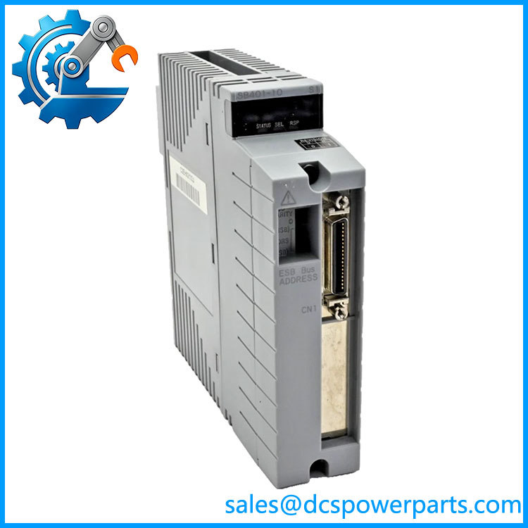
SB401-10
Defined accessory and wiring requirements
The module works within a specific ESB bus connection arrangement. The correct cable, connector unit, and termination hardware are part of the installation design. Confirm whether the existing assembly uses the required connector and terminator arrangement, and whether any adapter is needed for the replacement. This prevents avoidable commissioning delays caused by ordering the module without the required connection components.
Applications
Distributed I/O nodes in process plants
The -10 is used in compatible distributed control system installations where I/O modules are housed in a field control node separate from the main controller. The ESB communication path allows the controller to exchange process data with the node without placing every I/O module in the same physical cabinet.
Chemical and petrochemical facilities
In process facilities, distributed I/O nodes can serve equipment areas that contain a mix of analog measurement points and discrete control signals. The supports the communication infrastructure for a compatible node; it does not independently perform process control logic or provide safety certification for the connected application. Hazardous-area suitability must be determined from the complete installed equipment and its approved configuration.
Power generation and utility systems
Power and utility installations may use distributed I/O arrangements to connect process measurements and control signals to a central control system. Where the existing architecture uses the family, a replacement must preserve the approved ESB interface and node configuration. Verify the site’s drawings and parts list before using this model in an existing control cabinet.
Redundant control communication
The documented dual-module configuration makes the relevant to systems designed with redundant bus interfaces. During maintenance, confirm the active and standby path, identify the module being removed, and follow the site’s approved redundancy and changeover procedure. Do not remove both modules simultaneously unless the system procedure explicitly permits it.
Legacy-system maintenance
For plants maintaining established Yokogawa FIO hardware, the -10 may be required to restore a failed ESB interface without redesigning the node. Replacement planning should include the exact suffix, connector arrangement, node type, and available configuration records. If the installed hardware or software has been upgraded over its service life, obtain confirmation of compatibility before installing a substitute.
Related Products
The following models and accessories have documented roles in the surrounding Yokogawa ESB/FIO architecture. They are related components, not automatic substitutes he .
| Model | Function or relationship |
|---|---|
| ANB10S | Single-node ESB bus node unit |
| ANB10D | Dual-node ESB bus node unit |
| EC401 | ESB bus coupler module for compatible N-IO/FIO configurations |
| PW481 | Node-unit power supply module for 100–120 V AC input configurations |
| PW482 | Node-unit power supply module for 220–240 V AC input configurations |
| PW484 | Node-unit power supply module for 24 V DC input configurations |
| EB401 | ER bus interface master module used for a different communication role in compatible node architectures |
| ANT401 | Optical ESB bus repeater master module |
| ANT502 | Optical ESB bus repeater slave module |
Confirm system generation, connection requirements, and supported combinations in the applicable Yokogawa documentation.
Installation and Maintenance
Before removing an eng , review the node-unit drawings and the applicable Yokogawa maintenance procedure. Confirm which bus path the module serves and whether the node is operating in a redundant configuration. Follow site isolation and authorization procedures, and do not remove or insert modules under power unless the applicable hardware documentation explicitly allows it.
Inspect the replacement’s model label, connectors, contact surfaces, and housing. Look for bent contacts, cracked components, contamination, or evidence of unauthorized repair. Confirm the full suffix against the existing bill of materials. If the node requires two matching modules for redundancy, verify that both the model and approved configuration match the design.
Check the ESB cable and connector unit before installation. Inspect cable seating and connector condition, and verify the required termination arrangement. Avoid forcing connectors or substituting a cable based only on physical resemblance. Also confirm that the module is installed in the correct designated position for the node’s bus arrangement.
After installation, follow the approved startup and diagnostic procedure. Check the documented status indicators, confirm communication with the node’s I/O subsystem, and verify that the control system receives valid data. In redundant systems, check both paths according to the maintenance procedure and confirm that the intended redundancy state has been restored. Record the installed model, hardware identification, test results, and any corrective work in the maintenance log.
Product Assurance
For procurement of the Ywa , verify the full model code, physical condition, and compatibility with the intended node unit before accepting the part. The model designation identifies the ESB Bus Interface Slave Module, but it does not establish whether an individual unit is new, refurbished, previously repaired, or functionally tested.
Request clear nameplate photographs and confirmation of the exact suffix. If testing is offered, ask for the scope of the test, including whether the unit was checked for physical integrity, status indication, and communication in a compatible test setup. A visual inspection alone cannot establish correct bus communication.
For critical applications, confirm that the proposed replacement is suitable for the installed node model and the site’s redundancy arrangement. Check whether required cable connectors, termination components, or adapters are supplied separately. Establish the acceptance criteria, warranty terms, traceability documentation, and delivery schedule before purchase.
Availability and condition should be confirmed for the actual unit being quoted. The most useful procurement outcome is a correctly identified interface module with documented condition and a verified installation match—not simply a part number that appears similar to the one removed.