Description
Technical Specifications
| Parameter | Specification |
|---|---|
| Product model | S9361DH-00 |
| Manufacturer | Yokogawa |
| Product category | Terminal board module |
| System family | Legacy CENTUM systems; exact compatibility to be verified |
| Function | Field-wiring termination and signal interfacing |
| Terminal count | Reported as 16 points by one secondary listing; verify against the physical board |
| Connection type | Exact terminal and connector arrangement requires confirmation |
| Rated voltage | Not independently verified |
| Rated current | Not independently verified |
| Operating temperature | Not independently verified |
| Dimensions | Confirm from the board drawing or physical measurements |
| Weight | Supplier listings differ; confirm the supplied unit |
Important: Do not use generic terminal-board voltage, current, temperature, or channel ratings from unrelated product listings as approved engineering specifications. Confirm them against the applicable Yokogawa documentation and the installed board’s markings.
Product Overview
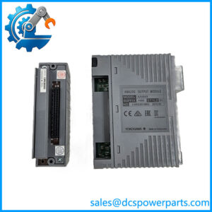
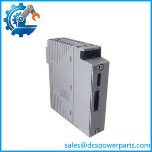
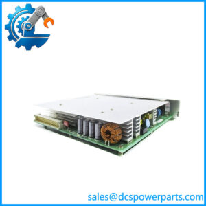
The Yokogawa S9361DH-00 is identified in industrial automation parts listings as a terminal board module associated with Yokogawa’s legacy distributed control system hardware. Terminal boards provide the physical interface between field wiring and the control system’s I/O hardware. Depending on the specific design, they can organize field connections, provide defined termination points, and route signals through a compatible cable or connector assembly.
In a maintenance environment, correct terminal-board identification is important because a physically similar board may use a different connector arrangement, wiring assignment, or signal configuration. The model S9361DH-00 should therefore be selected by its full part number and verified against the cabinet drawings, installed I/O hardware, and original bill of materials. A general description such as “Yokogawa terminal board” is not sufficient to establish interchangeability.
The model is associated with legacy Yokogawa control-system equipment in secondary listings, but a definitive manufacturer specification establishing its exact system compatibility and electrical ratings was not confirmed in the available sources. For that reason, the terminal count, operating limits, and detailed interface characteristics should be checked before the board is used in a live installation.
For procurement teams supporting older DCS installations, the practical priority is to match the physical board and its electrical interface rather than assume that a newer terminal board can replace it. Confirm the nameplate, connector keying, mounting arrangement, wiring diagram, and associated I/O module before releasing the part for installation.
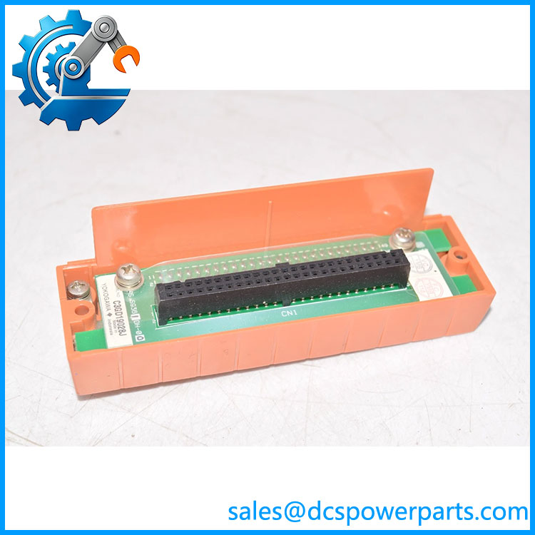
S9361DH-00
Major Features and Advantages
1. Field-wiring termination
The primary role associated with the S9361DH-00 is terminal-board interfacing. A suitable terminal board provides an organized connection point for field conductors and the corresponding control-system interface. The exact signal types and circuit groupings supported by this model must be established from its wiring documentation.
2. Support for legacy-system maintenance
When a control system has been in service for many years, replacing a failed or damaged connection board with the correct part can reduce the scope of cabinet rewiring. Matching the original model helps maintenance teams preserve the existing connection arrangement, provided that the replacement’s revision and condition are acceptable.
3. Configuration-specific connectivity
Terminal boards are not universally interchangeable. Connector layout, pin assignment, terminal numbering, and the associated I/O module determine whether a board is appropriate for a given application. The S9361DH-00 should be cross-checked against the installed assembly before purchase, especially where legacy drawings or previous field modifications may be incomplete.
4. Practical replacement assessment
A replacement assessment should cover the board’s physical condition, contact integrity, terminal security, mounting points, and identification markings. If the unit has been stored for an extended period, inspect it for corrosion, contamination, damaged contacts, and signs of moisture exposure. These checks are more meaningful than relying solely on a supplier’s generic claim that a component is suitable for industrial use.
5. Traceable procurement
For discontinued or legacy components, a clear record of the model number, supplied condition, inspection findings, and any available functional test evidence helps reduce procurement risk. If the part is described as new, refurbished, or used, the supplier should state the actual condition of the specific unit rather than rely on a standard product description.
Applications
The S9361DH-00 may be relevant to maintenance work on compatible legacy Yokogawa DCS cabinets where a terminal-board replacement is required. Typical maintenance scenarios include repairing a damaged termination assembly, restoring an existing field-wiring interface, or retaining an established cabinet configuration during a planned outage.
Before assigning it to a process-control application, identify the I/O hardware and field circuits connected to the original board. The board’s role may differ according to the system configuration, so it should not be assumed to support analog inputs, analog outputs, digital signals, or any particular voltage level without the applicable wiring diagram.
In retrofit projects, the main question is whether the existing field wiring and the proposed replacement have matching electrical and mechanical interfaces. A newer terminal board may look similar but require a different cable, connector, or I/O module. Any substitution should be reviewed against the control-system drawings and validated through the site’s engineering change process.
For spare-parts planning, record the full designation and photograph the installed unit’s label, connectors, terminal markings, and mounting details. These records help distinguish the required component from similarly named boards and reduce the chance of ordering an incompatible replacement. Final acceptance should depend on confirmed fit, documented electrical suitability, and inspection—not on a broad claim of compatibility with the Yokogawa CENTUM family.
Related Products and Components
The following are related categories or models referenced in secondary listings; their suitability for a particular installation must be confirmed.
| Product or component | Relationship |
|---|---|
| S9260DE-01 | Listed as a related legacy terminal-board model; not confirmed as interchangeable. |
| S9185FA | Listed in connection with other legacy terminal-board hardware; exact relationship requires verification. |
| Yokogawa CENTUM XL | Legacy control-system family associated with the in a secondary listing. |
| Yokogawa CENTUM CS | Legacy control-system family referenced in secondary product descriptions. |
| Compatible I/O module | The specific module must be identified from the cabinet drawings and original configuration. |
| Mating system cable | Must match the board’s actual connector and pin assignment. |
These associations are not a substitute for a manufacturer compatibility table or approved replacement cross-reference.
Installation and Maintenance
Before installing the , verify the part number against the installed board and approved cabinet documentation. Record connector positions, terminal labels, wiring assignments, and any visible revision markings before disconnecting conductors. Follow site lockout, isolation, and electrical safety procedures; never remove or replace a board in an energized assembly unless the system’s approved procedure explicitly permits it.
Inspect the replacement for damaged terminals, bent contacts, corrosion, contamination, cracked board material, and loose hardware. Compare its mounting points and connector layout with the original. Do not force a connector or modify wiring to make a visually similar board fit.
After installation, check termination security and verify each affected circuit against the approved wiring diagram. Perform continuity or functional checks using the site’s commissioning procedure, then confirm that the associated I/O channels report the expected status or signal. Where the connected circuits are safety-critical or affect process shutdowns, complete the required independent verification before returning the system to service.
Record the replacement date, part number, condition, inspection results, and any deviations found during commissioning. If the exact electrical ratings or system compatibility cannot be established, hold the board from service until the relevant documentation is obtained.
Product Assurance
For procurement of the Yokogawa , the key assurance points are part-number accuracy, physical condition, interface compatibility, and traceable inspection. Request photographs of the actual unit’s label and connector side, not only a representative product image. For a used or refurbished board, ask for the condition classification and the scope of any testing performed.
A supplier’s statement that the product is “tested” should be supported by details of what was tested. Visual inspection alone does not establish electrical suitability or prove correct operation in the target control system. Similarly, a general warranty does not establish compatibility with a particular I/O assembly.
Before purchase, confirm the supplied quantity, included accessories, warranty terms, return conditions, and lead time. Most importantly, compare the exact board with the installed hardware and engineering records. The available sources support identifying as a Yokogawa terminal board, but they do not establish enough verified electrical data to safely specify it beyond that role without further documentation.