Description
Technical Specifications
| Parameter | Specification |
|---|---|
| Product Model | PW484-10 — verify exact nameplate designation |
| Manufacturer | Yokogawa Electric Corporation |
| Product Type | Dedicated system power supply module |
| Input Voltage | 24 V DC ±10% |
| Maximum Power Consumption | 5.5 A |
| Output Power | Not specified as a general-purpose output rating |
| Interface | Dedicated system connector |
| Supported Installation Units | Compatible FCU, FIO Node Unit, Optical ESB Bus Repeater Unit |
| Mounting Position | Power supply slots P1–P2 where supported |
| Redundant Operation | Two identical modules with matching model codes |
| Approximate Weight | 1 kg |
| Protection / Environmental Option | Must be confirmed from the complete suffix and nameplate |
Yokogawa explicitly states that the PW48 series is designed for its specified control-system units and must not be treated as a general-purpose power supply. Its output voltage and current are not specified as standalone supply ratings.
Product Overview
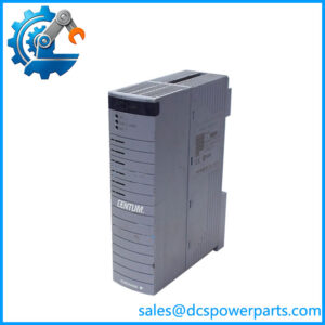
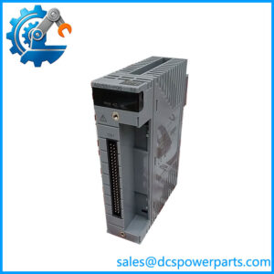
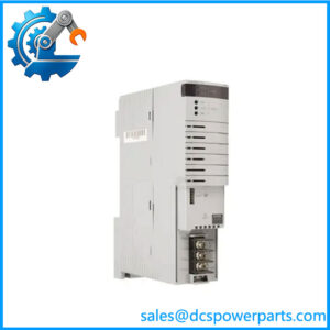
The Yokogawa PW484-10 is associated with the PW484 family of dedicated 24 V DC input power supply modules used in compatible Yokogawa distributed control system hardware. Its role is to provide the required power interface within designated Field Control Units, FIO Node Units, and Optical ESB Bus Repeater Units. It is a system-specific component, not a universal DIN-rail power supply for arbitrary 24 V DC loads.
The published specification for the PW484 family gives an input voltage of 24 V DC ±10% and maximum power consumption of 5.5 A. Yokogawa does not specify a generic output voltage and current rating for this module because it is intended for designated system hardware. Buyers should therefore avoid assuming that the module can directly replace a conventional 24 V DC power supply, even if the input voltage appears identical.
The PW484 family supports dual-redundant power arrangements in compatible installations. The documented configuration uses two identical modules with matching model codes in the designated power supply positions. Redundancy depends on the complete installation, including compatible base hardware, correct power distribution, and the system’s approved configuration. Installing two visually similar modules is not sufficient to establish a valid redundant arrangement.
There is an important procurement consideration with PW484-10: current published Yokogawa ordering information uses suffix formats such as -50 and -51, while some supplier catalogs still list -10. Before ordering a replacement, compare the installed module’s nameplate, hardware identification, and system parts list. Do not assume that a different suffix is interchangeable without confirmation from the applicable documentation or the system integrator.
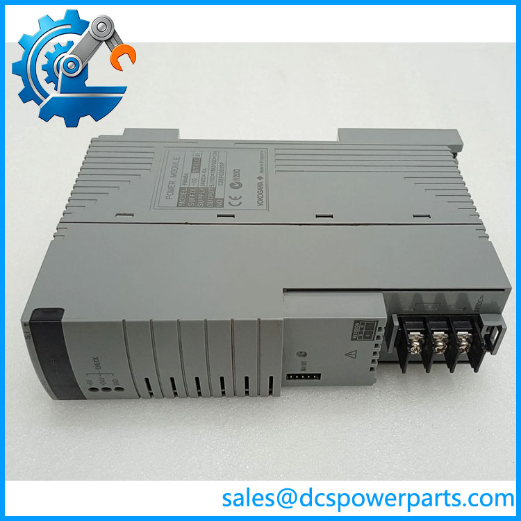
PW484-10
Major Features and Advantages
Dedicated power interface for Yokogawa hardware
The family is intended for specified Yokogawa control-system assemblies. This dedicated design supports integration with the appropriate system power and connector arrangement. It also means that installation compatibility must be checked against the receiving unit rather than judged by input voltage alone.
24 V DC input
The published input range is 24 V DC ±10%, equivalent to 21.6–26.4 V DC. Verifying the actual DC supply at the module terminals is a practical first step when investigating power-related faults. Voltage drop, poor connections, supply instability, and incorrect wiring can affect operation even when the nominal plant supply is 24 V DC.
Dual-redundant configuration support
In a supported installation, two identical power supply modules can be installed to provide dual redundancy. This can reduce dependence on a single module, but it does not eliminate failures in shared upstream supplies, connectors, base hardware, or downstream distribution. The site’s engineering documentation should define the expected redundancy behavior and acceptance tests.
Compatibility with multiple system-unit types
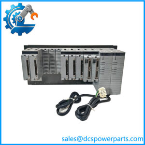
The family is documented for compatible FCUs, FIO Node Units, and Optical ESB Bus Repeater Units. This allows the module to serve different roles within supported Yokogawa system assemblies. The permitted unit models and slot assignments must still be checked against the applicable hardware specification.
Model-code verification for maintenance procurement
The distinction between -10 and the published suffix-coded variants is material. Verifying the exact code before purchase helps avoid receiving a part that fits physically but does not match the required system configuration. A supplier’s description of an updated or replacement model should be treated as a compatibility claim requiring confirmation, not as proof of direct interchangeability.
Applications
Field Control Units
Compatible Field Control Units use dedicated power modules as part of the control-system hardware assembly. In a replacement project, confirm the FCU model, supported power module, and installed slot arrangement before procurement. The family is relevant only where the unit’s documentation permits the 24 V DC input version.
FIO Node Units
Distributed I/O nodes use power modules as part of their system hardware. A suitable -family module can support an installation that requires the specified 24 V DC input configuration. Before replacement, check the node model, installed modules, and whether the system uses one supply module or a dual-redundant pair.
Optical ESB Bus Repeater Units
Compatible optical ESB repeater units are another documented installation category for the PW48 series. In these applications, power-module compatibility is part of the repeater assembly’s hardware requirements. Confirm the exact repeater model and its power-slot arrangement rather than assuming every unit accepts every suffix.
Control-system maintenance and spare-parts programs
The -10 may appear in older maintenance records or supplier inventories. Where the installed hardware uses this designation, capture the complete nameplate details and compare them with the current bill of materials before sourcing a replacement. If a supplier proposes -50 or another suffix, obtain confirmation that the proposed unit is approved for the exact installation.
Redundant power-system maintenance
Where dual redundancy is implemented, maintenance planning should account for the status of both modules and the expected behavior during a module failure. Verify that the replacement matches the installed model code and follow the approved procedure for removing, installing, and testing the module. Do not infer successful redundancy merely because the system remains powered after a swap.
Related Products
| Model | Function or relationship |
|---|---|
| PW481 | 100–120 V AC input power supply module |
| PW482 | 220–240 V AC input power supply module |
| 24 V DC input power supply module family | |
| -50 | Published suffix-coded version for 24 V DC input |
| -51 | Published suffix-coded version with the G3 temperature option |
| ANB10S | Single-node FIO ESB bus node unit |
| ANB10D | Dual-node FIO ESB bus node unit |
| ANB11S | Single-node optical ESB bus node unit |
| ANB11D | Dual-node optical ESB bus node unit |
| ANT10U | Optical ESB bus repeater unit |
These models are related by product family or documented installation role. They are not direct substitutes he . Verify the exact supported combination using the receiving unit’s hardware documentation.
Installation and Maintenance
Before removing or repl a , identify the receiving unit and verify the complete model code from the installed module’s label. Follow the plant’s electrical isolation and lockout procedures. Do not insert or remove the module under power unless the applicable Yokogawa instructions explicitly permit that operation.
Measure and verify the DC input supply within the published 21.6–26.4 V range. Inspect the power wiring, dedicated connector, module contacts, and receiving slot for looseness, contamination, heat damage, or mechanical wear. Check the system’s installation drawings to establish the correct power slot. For a single-module arrangement, the published installation guidance specifies slot P1; redundant arrangements use the designated P1–P2 positions with two identical modules.
After installation, follow the documented startup and diagnostic procedure. Confirm that the receiving unit recognizes the power module and that the expected system status is restored. Where redundancy is installed, test the configuration according to the site’s approved maintenance procedure rather than performing an unplanned power interruption.
Record the module code, hardware identification, test results, and any changes to the installation. If the replacement has a different suffix, retain written compatibility confirmation with the maintenance records.
Product Assurance
For procurement of the Ywa , the main acceptance criteria are correct identity, compatibility with the receiving unit, physical condition, and documented testing. The part number alone does not establish whether an individual unit is new, refurbished, previously repaired, or tested.
Request a clear nameplate photograph and confirmation of the exact model and suffix. If the offered part is identified as an updated or replacement version, ask for explicit confirmation that it is compatible with the installed FCU, FIO Node Unit, or Optical ESB Bus Repeater Unit. The published family specifications should be used to verify the electrical input requirements, but they do not establish that every historical part designation is interchangeable.
If functional testing is offered, clarify the test scope and whether the module was evaluated in compatible system hardware. A visual inspection or an input-voltage check alone cannot demonstrate correct operation in the intended installation. For redundant systems, confirm the acceptance procedure for both the individual module and the installed redundant arrangement.
Finally, confirm the supplied condition, warranty terms, traceability documentation, and delivery schedule for the actual unit being quoted. This is particularly important when sourcing older suffix variants or a proposed replacement model