Description
Technical Specifications
| Parameter | Specification |
|---|---|
| Manufacturer | Yokogawa Electric Corporation |
| Product Model | PW482-10 S2 |
| Product Type | AC-input power supply module |
| Input Voltage | 220–240 V AC ±10% |
| Input Frequency | 50/60 Hz ±3 Hz |
| Maximum Power Consumption | 230 VA |
| Input/Output Interface | Dedicated Yokogawa connector |
| Installation | Compatible FCU, FIO Node Unit, or Optical ESB Bus Repeater Unit |
| Mounting Slots | P1–P2; exact slot requirements depend on the host unit |
| Redundant Configuration | Two identical compatible modules |
| Approximate Weight | 1 kg |
| Output Voltage and Current | Not specified as generic power-supply ratings; depend on the intended Yokogawa system |
| Style / Suffix | Confirm full nameplate, including S2 and all suffix codes |
Yokogawa’s official general specification identifies the PW482 as the 220–240 V AC input variant in the PW481/PW482/PW484 family. It also states that these modules are dedicated to specified Yokogawa control-system hardware and should not be treated as generic power supplies.
Important model distinction: PW481 is the 100–120 V AC variant, PW482 is the 220–240 V AC variant, and PW484 is the 24 V DC input variant. Do not substitute between these models based only on physical fit. The exact meaning of the additional S2 designation should be verified against the module’s nameplate and applicable hardware documentation.
Product Overview
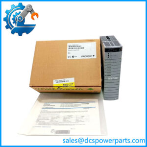
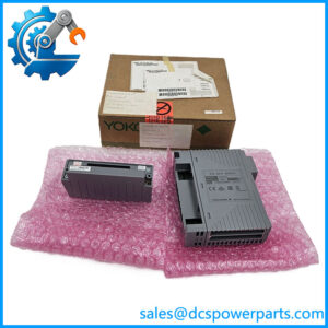
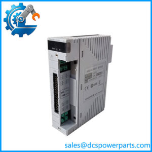
The Yokogawa PW482-10 S2 is a dedicated power supply module designed for compatible Yokogawa control-system hardware. It accepts 220–240 V AC input and supplies the power required by supported Field Control Units, FIO Node Units, and Optical ESB Bus Repeater Units. Its function is specific to the intended Yokogawa hardware architecture; it should not be treated as a standalone, general-purpose DC power supply.
The PW481/PW482/PW484 family covers different input-power arrangements. The is intended for 220–240 V AC, while the PW481 covers 100–120 V AC and the PW484 uses 24 V DC input. Yokogawa specifies a maximum power consumption of 230 VA for the and an approximate module weight of 1 kg. The manufacturer does not specify the module’s output voltage and current as generic power-supply ratings because the unit is designed for use within designated control-system hardware.
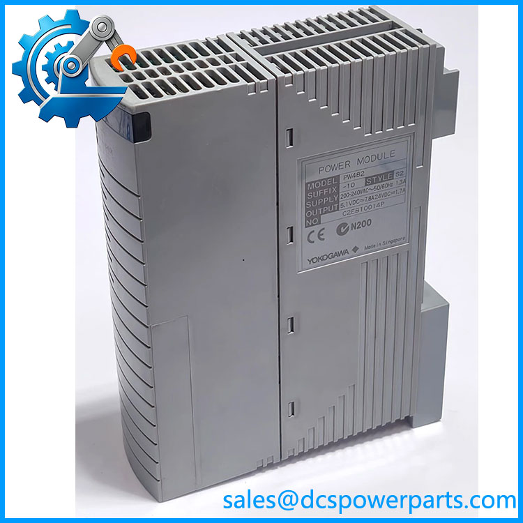
PW482-10 S2
The supports dual-redundant power configurations when two identical, compatible modules are installed in the designated positions. This arrangement can help maintain system power availability if one supply path fails, provided the host unit and power architecture support redundancy. The actual installation procedure and slot assignment must be confirmed for the specific FCU, node unit, or repeater.
For maintenance and procurement, the key checks are the complete model designation, AC input range, style and suffix markings, host hardware, and required redundancy arrangement. The S2 designation should be matched against the installed unit rather than interpreted from reseller descriptions alone. Verifying these details before shipment helps avoid receiving a module that fits the hardware but does not match the electrical or configuration requirements.
Major Features and Advantages
Dedicated AC input for compatible Yokogawa systems
The -10 S2 is intended for control-system equipment designed around the ‘s 220–240 V AC input. Matching the input range to the site’s power supply is essential. It should not be substituted for the PW481 or PW484 without confirming the host hardware and power design.
Support for multiple system-unit types
Yokogawa documents the family for installation in compatible FCUs, FIO Node Units, and Optical ESB Bus Repeater Units. This gives maintenance teams a defined replacement option across supported system configurations. Compatibility still depends on the particular unit model, mounting position, and applicable hardware documentation.
Dual-redundant power configuration
Two identical power supply modules can be used in supported redundant configurations. Yokogawa specifies that the modules must have matching model codes. The presence of two supplies alone does not prove that the installation is redundant; the host unit, designated slots, input feeds, and wiring must also conform to the approved design.
Dedicated connector interface
The module uses a dedicated input/output connector for the intended Yokogawa hardware. This helps maintain the designed mechanical and electrical interface but also limits its use outside supported equipment. Do not adapt the connector or attempt to use the module as an independent power source without manufacturer-approved documentation.
Clear procurement checks
The most useful advantage during replacement is retaining the intended power-supply arrangement without redesigning the host unit. That outcome depends on confirming the complete model code and style, checking the host equipment, and establishing the actual condition of the supplied unit. A base-model match is necessary but does not establish functional condition or full interchangeability.
Applications
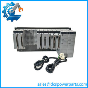
The Yokogawa -10 S2 is intended for compatible control-system installations requiring a 220–240 V AC input power supply module. Typical locations include FCU racks, FIO Node Units, and Optical ESB Bus Repeater Units that explicitly support the family.
In a process plant, the power supply module is part of the infrastructure supporting controller operation and I/O communication. A power-supply fault can affect more than one downstream function, depending on the host unit and system configuration. Maintenance personnel should therefore investigate input power, the module, connectors, host-unit diagnostics, and other relevant power paths before deciding that the module itself is the root cause.
The is also relevant to spare-parts planning for installations using dual-redundant power. A replacement should match the existing model code and be suitable for the installed unit. If the plant relies on redundant supplies, the maintenance team should verify both modules and the intended power-feed arrangement under the approved test procedure. Redundancy should not be assumed to eliminate every power-related failure mode.
For system expansion or hardware replacement, engineers should confirm the required input voltage and the specific FCU or node-unit configuration. The is not interchangeable with the PW481 merely because both accept AC input, nor with the PW484, which is designed for 24 V DC input. The host hardware and electrical requirements determine the appropriate selection.
For critical-spares inventory, record the complete model and suffix, host-unit model, mounting position, and redundancy requirement. This information helps procurement distinguish the correct spare from similar-looking modules and reduces the risk of a delayed repair caused by an incorrect input-power variant.
Related Products
| Model | Relationship |
|---|---|
| AFV30S / AFV30D | Base 220–240 V AC input power supply model |
| AFV30S / AFV30D | Related 100–120 V AC input power supply module |
| AFV30S / AFV30D | Related 24 V DC input power supply module |
| AFV30S / AFV30D | FCU family documented for compatible PW48-series installations |
| A2FV50S / A2FV50D | FCU family documented for compatible PW48-series installations |
| A2FV70S / A2FV70D | FCU family documented for compatible PW48-series installations |
| ANB10S / ANB10D | FIO Node Unit family |
| ANB11S / ANB11D | FIO Node Unit family |
| ANT10U | Optical ESB Bus Repeater Unit |
These models are related by system architecture or power-supply application. Compatibility must be verified against the applicable hardware documentation before substitution.
Installation and Maintenance
Before installing the -10 S2, verify the nameplate and confirm that the available input supply is within the specified 220–240 V AC ±10% range. Check the input frequency, host-unit model, mounting position, and full style and suffix markings. Do not infer electrical ratings from the module’s appearance or from a description that omits the complete part number.
Follow the site’s approved electrical isolation and lockout procedures before removing the module. AC input presents a hazardous voltage; installation and testing should be performed by qualified personnel using the applicable Yokogawa instructions. Confirm that the dedicated connector and mounting interface are undamaged and correctly seated. Do not modify wiring or connectors to make an incompatible module fit.
For a redundant installation, verify that the replacement matches the existing module code and that the host unit is designed for two-module operation. Check the approved slot assignments and power-feed arrangement. Do not remove a supply from an energized system unless the documented procedure specifically permits it and the operational risk has been assessed.
After installation, follow the host unit’s prescribed startup and diagnostic checks. Confirm that the power-supply status is normal and that the associated controller, I/O node, or repeater returns to the expected operating state. If the system does not recover, investigate the incoming supply, connectors, host-unit status, and related hardware rather than assuming the replacement module is defective.
Record the replacement model, serial or identification details, test results, and any observed faults in the maintenance history. For critical equipment, use documented acceptance criteria and avoid relying solely on a visual inspection.
Product Assurance
For the Yoko S2, product assurance should begin with exact part identification. Request clear photographs of the nameplate, suffix markings, connector, and overall module condition. Compare these details with the installed unit and the applicable system documentation before accepting the part as a replacement.
The technical description establishes the ‘s intended AC input and system role; it does not establish the condition of an individual unit. New surplus, used, and refurbished modules should be identified accurately, and any testing claims should specify what was actually performed. A visual inspection alone is not proof of electrical or functional performance.
For a critical spare, request available test records, confirm warranty and return terms, and establish the expected delivery lead time before purchase. If a different suffix or style is proposed, require documented compatibility confirmation rather than assuming it is equivalent.
Final acceptance should consider the full model designation, input voltage, host-unit compatibility, physical condition, and available test evidence. These checks reduce the risk of installing a module that appears correct but does not meet the requirements of the existing control-system power arrangement.