Description
Technical Specifications
| Parameter | Specification |
|---|---|
| Model | PW481-50 S2 |
| Manufacturer | Yokogawa |
| Product type | Dedicated AC-input power supply module |
| Nominal input voltage | 100–120 V AC |
| Permitted input range | 90–132 V AC (±10% of the 100–120 V range) |
| Input frequency | 50/60 Hz ±3 Hz |
| Maximum power consumption | 200 VA |
| Electrical connection | Dedicated module connector |
| Approximate module weight | 1 kg |
| Redundant operation | Supported with two compatible modules |
| Supported equipment | Compatible FCU, FIO node unit, and optical ESB bus repeater unit |
| Output voltage/current | Not specified as a general-purpose power supply; use the applicable system documentation |
| Operating temperature | Verify against the installation manual for the host assembly and exact hardware style |
| Product condition | Confirm with the supplier for the individual unit |
The electrical ratings above are based on Yokogawa’s PW481/PW482/PW484 general specifications. The PW481 is the 100–120 V AC variant; PW482 is the 220–240 V AC variant, and PW484 is the 24 V DC variant. These models should not be substituted for one another without checking the installed system’s requirements.
Product Overview
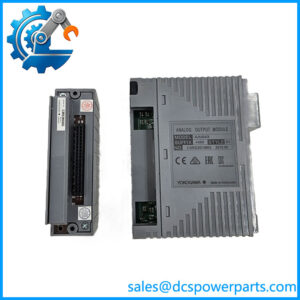
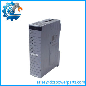
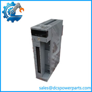
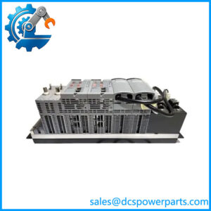
The Yokogawa PW481-50 S2 is a dedicated power supply module for compatible Yokogawa distributed control system hardware. It is designed for installations that use the PW481 AC-input power supply within Field Control Units (FCUs), FIO node units, and optical ESB bus repeater units. Its specified input is 100–120 V AC, making correct input-voltage identification an essential procurement and maintenance check.
Unlike a standalone DIN-rail power supply, the PW481-50 S2 is intended for a defined Yokogawa equipment platform. It connects through the system’s dedicated interface and must be installed in a supported host assembly. Yokogawa’s general specifications describe the family as dedicated power modules and explicitly state that output voltage and current are not specified for generic power-supply use. For this reason, it should not be selected as a general-purpose source for external instruments or field loads.
The module supports dual-redundant power arrangements when two compatible units are installed in the designated positions. This configuration can help a properly designed control system maintain power availability if one supply module fails. Redundancy depends on the host hardware, correct module pairing, upstream AC supply, and the system’s approved installation procedure; the presence of two modules alone does not guarantee uninterrupted operation.
When sourcing a replacement, confirm the complete -50 S2 designation, the required input-voltage class, and compatibility with the existing FCU, FIO node, or optical ESB repeater assembly. The hardware style and suffix should be checked against the installed system documentation. A supplier’s description of a similar variant is not sufficient evidence that it is an approved replacement.
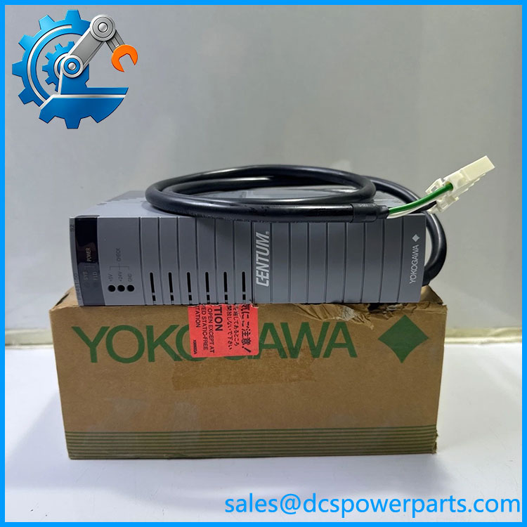
PW481-50 S2
Major Features and Advantages
Dedicated Yokogawa system integration
The -50 S2 is designed for specific Yokogawa control-system assemblies rather than universal power distribution. Its dedicated connector and host-module compatibility are important when planning replacements, maintaining spare inventory, or restoring a control cabinet after a power-related fault.
Defined AC input requirements
The family is specified for 100–120 V AC input, with a tolerance of ±10% and a frequency range of 50/60 Hz ±3 Hz. Maximum power consumption is specified at 200 VA. These values provide a basis for checking the supply circuit and identifying the correct model variant before installation. They should not be confused with a rated external DC output.
Support for redundant power configurations
Yokogawa documents dual-redundant operation using two power supply modules in supported equipment. This arrangement is relevant to control systems where an individual module failure must not unnecessarily interrupt controller or remote-I/O operation. Confirm the designated slots, matching model codes, and redundancy requirements for the exact host assembly before replacing either module.
Compact module format
The manufacturer’s general specification gives an approximate module weight of 1 kg and provides a dedicated mechanical outline. These details are useful for spare-parts handling and preliminary maintenance planning. For actual cabinet fit, clearances, and removal procedures, use the official mechanical drawing and installation guidance rather than measurements copied from unrelated product listings.
Clear distinction between power-supply variants
The broader PW48x family includes the for 100–120 V AC, PW482 for 220–240 V AC, and PW484 for 24 V DC. Identifying the wrong input variant can prevent a replacement from operating correctly and may create an electrical hazard. The model number and installed supply source should therefore be checked together during procurement.
Applications
CENTUM VP Field Control Units
The -50 S2 can be used in compatible Yokogawa FCU configurations. These units form part of the distributed control architecture responsible for executing control functions and communicating with process I/O. The power module is a supporting hardware component; it does not replace the controller processor, communication module, or I/O card.
FIO node units
In supported FIO node assemblies, the provides the designated power-supply function for the equipment. When a node develops a power-related alarm or fails to start, maintenance personnel should check the incoming AC source, module seating, host-unit status, and associated diagnostics before concluding that the power supply itself has failed.
Optical ESB bus repeater units
Yokogawa identifies the family for use in compatible optical ESB bus repeater equipment. This makes the module relevant to distributed installations where communication equipment is located away from the main control unit. The repeater’s communication function and the power supply’s electrical function remain separate, so a communication failure should not automatically be attributed to the supply module.
Planned maintenance and spare-parts management
Plants operating Yokogawa control systems may keep a verified replacement available to reduce repair delays. Spare inventory should distinguish the 100–120 V AC from the 220–240 V AC PW482 and 24 V DC PW484. It should also record the full style designation and any site-specific approval or revision requirements.
Before returning a repaired or replacement unit to service, verify the host configuration and confirm that the system has returned to its expected operating state. Where redundant power is installed, follow the site’s approved procedure for checking the healthy supply, alarms, and load-sharing or standby behavior.
Related Products
The following products are associated with the same Yokogawa power-supply family or compatible equipment environment. They have different roles or input requirements and should not be treated as automatic substitutes.
| Model | Relationship |
|---|---|
| Base 100–120 V AC power supply module family designation. | |
| PW482 | Related power supply module for 220–240 V AC input; different input-voltage class. |
| PW484 | Related power supply module for 24 V DC input. |
| AFV30D | Yokogawa duplexed Field Control Unit family that uses supported power modules. |
| AFV30S | Yokogawa simplex Field Control Unit family. |
| ANB10 | ESB bus node unit family with supported power-module configurations. |
| ANB11 | Optical ESB bus node unit family with supported power-module configurations. |
| ANT10U | Optical ESB bus repeater unit that supports designated PW48x power modules. |
The host equipment and module relationships are documented in Yokogawa’s power supply specifications and related installation information. Confirm the exact host model, supply voltage, and required module style before ordering.
Installation and Maintenance
Before instal S2, isolate the relevant power source according to the plant’s electrical safety procedures. Verify that the cabinet supply matches the module’s 100–120 V AC input rating and that the receiving FCU, FIO node, or optical ESB repeater assembly supports the selected model. Do not install a PW482 or PW484 simply because it belongs to the same product family.
Check the module label, connector condition, housing, and visible signs of overheating or physical damage. Inspect the host slot for contamination or damage and confirm the approved installation position. Yokogawa documentation specifies designated power-module positions and requires compatible modules for dual-redundant configurations; follow the relevant installation guidance for the exact host assembly.
If a supply fault is suspected, check the incoming AC source and system diagnostics before replacing the module. A failed upstream circuit, loose connection, host-unit problem, or downstream fault may produce symptoms similar to a defective power supply. In a redundant installation, do not assume that the system can tolerate module removal without interruption; follow the site’s approved maintenance procedure.
After installation, verify the module status and confirm that the host equipment starts and operates normally. Check for remaining power alarms and confirm that the expected controller or node functions are available. Record the installed part number, condition, fault symptoms, and test results in the maintenance history.
Product Assurance
For procuremen S2, part-number accuracy and electrical compatibility should be confirmed before shipment. The manufacturer’s specifications establish the family’s input-voltage class and intended host applications, but they do not establish the condition, authenticity, or test history of any particular unit offered by a supplier.
Recommended incoming checks include:
- Model verification: Confirm the comp S2 marking against the purchase order and approved spare-parts list.
- Input-voltage confirmation: Verify that the installation requires the 100–120 V AC variant.
- Physical inspection: Check the module housing, connectors, and labels for damage or alteration.
- Test documentation: Request inspection or functional-test records and clarify what equipment was used for testing.
- Condition disclosure: Obtain written confirmation of whether the supplied unit is new, used, or refurbished.
- Compatibility review: Confirm support for the intended host assembly and any redundant-power requirements.
For a control system supporting a continuous process, a replacement should be accepted based on documented condition, correct configuration, and suitable test evidence—not the model label alone. Confirm warranty terms and the supplier’s return procedure before purchasing, especially when the original module is difficult to source.