Description
Product Overview
The Yokogawa GRVSW-664FA provides Ethernet switching for industrial control networks where dependable communication between control-system domains, stations, and connected infrastructure is required. In a Yokogawa Vnet/IP installation, the switch forms part of the communications layer rather than performing controller logic or field-signal processing. Correct selection therefore depends on the network design, port assignments, approved configuration, and the requirements of the connected control-system equipment.
This model belongs to the MACH104 family and uses a redundant AC power-input arrangement. Yokogawa’s technical documentation identifies two power inlets, P1 and P2, and notes that both should be used on the redundant-power version; otherwise, the switch can report a power-failure condition. This matters during replacement planning: a spare with the wrong power configuration is not necessarily a suitable substitute, even when its enclosure and port layout appear similar.
For maintenance teams, the main procurement risk is not simply whether the switch powers up. Confirm the full GRVSW-664FA nameplate, port layout, installed SFP modules, approved Vnet/IP configuration, and condition of both power inputs before installation. A generic managed Ethernet switch should not be assumed equivalent just because its port count matches. The replacement should be checked against the site’s network engineering standards and commissioning procedure.
Product Introduction
The Yokogawa GRVSW-664FA is designed for rack-mounted industrial Ethernet applications requiring multiple copper connections, fiber connectivity through SFP interfaces, and redundant AC power. Its management interfaces and status indicators support network configuration and troubleshooting. The switch’s intended role is to support the communications infrastructure for Vnet/IP-based control environments, not to replace a controller, I/O module, or safety-system processor.
When purchasing a replacement, compare the exact model suffix and hardware configuration with the installed unit. Verify the network configuration and SFP specifications separately; do not assume that a used switch retains the configuration of the unit it replaces.
Key Technical Specifications
| Specification | Details |
|---|---|
| Product model | GRVSW-664FA |
| Manufacturer | Yokogawa |
| Product type | Managed Layer 2 Ethernet switch |
| Hardware family | MACH104 |
| Vendor hardware model | MACH104-20TX-FR |
| Intended network | Yokogawa Vnet/IP |
| RJ-45 ports | 24 |
| SFP ports | 4 listed for this configuration |
| Power input | Dual AC inputs, P1 and P2 |
| AC input voltage | 100–240 VAC |
| Input frequency | 47–63 Hz, per published MACH104 family specifications |
| Maximum power consumption | Approximately 35 W |
| Mounting method | 19-inch rack |
| Dimensions | Approximately 448 × 44 × 345 mm |
| Protection rating | IP30 |
| Operating temperature | 0 to 50°C |
| Storage temperature | −20 to 85°C |
| Fault contact rating | Up to 1 A, 60 VDC |
| Installation condition | Confirm rack, grounding, cabling, and site environmental requirements |
| Product condition | Confirm actual condition with supplier |
Specifications are based on published MACH104-family documentation and model-specific listings. Confirm the exact hardware revision and official installation documentation before using these values for panel design or replacement approval.
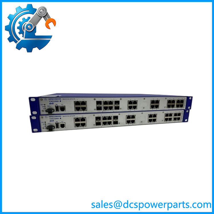
GRVSW-664FA
Related Products
The following models are useful comparison points within Yokogawa’s network-switch range. They should not be treated as automatic drop-in replacements.
| Model | Description / relationship |
|---|---|
| GRVSW-663FA | MACH104-family Layer 2 switch with a single AC power input |
| GRVSW-665FA | MAR1040-family Layer 2 switch with AC power |
| GRVSW-666FA | MAR1040-family Layer 2 switch with redundant AC power |
| GRVSW-668FA | MAR1040-family Layer 3 switch associated with BUS1 |
| GRVSW-669FA | MAR1040-family Layer 3 switch with redundant AC power, associated with BUS1 |
The model distinctions and power configurations are documented in Yokogawa’s network-switch technical information. Confirm port layout, switching function, and network role before considering any alternate model.
Frequently Asked Questions
Q1: What is the Yokogawa GRVSW-664FA used for?
It is a managed Layer 2 Ethernet switch intended for industrial control networking, including Yokogawa Vnet/IP infrastructure. It provides network connectivity rather than performing PLC logic or direct field I/O processing.
Q2: Does the GRVSW-664FA support redundant power?
Yes. Its -20TX-FR configuration has two AC power inputs, P1 and P2. Yokogawa’s documentation indicates that both inputs should be connected in the redundant-power configuration to avoid a power-failure indication.
Q3: Can the GRVSW-663FA replace the ?
Not without an engineering review. The GRVSW-663FA is identified as the single-AC-input version, while the has redundant AC inputs. A replacement decision must account for power redundancy, network configuration, and the installed system’s requirements.
Q4: How many network ports does the have?
Published specifications list 24 RJ-45 Ethernet ports and 4 SFP ports. Confirm the actual front-panel layout and SFP requirements on the unit being supplied.
Q5: Is the suitable for every industrial Ethernet network?
No. Physical Ethernet connectivity does not establish compatibility with every control network. Confirm the required protocols, network topology, management configuration, and any Yokogawa-specific Vnet/IP requirements before deployment.
Q6: Can this switch be installed while the control system is running?
Do not assume online replacement is permitted. A switch change can interrupt network communications, even if the replacement unit is powered independently. Follow the site’s approved maintenance procedure, redundancy design, and commissioning plan.
Q7: What should procurement verify before ordering?
Confirm the complete model number, hardware revision, dual-power functionality, port and SFP configuration, physical condition, configuration-reset status, and test evidence. For a used unit, request photographs of the nameplate and front and rear panels. Also confirm whether the switch has been tested under load and whether the required network configuration can be restored before installation.