Description
Technical Specifications
| Parameter | Specification |
|---|---|
| Manufacturer | Yokogawa |
| Product Model | EC401-10 S2 |
| Product Type | ESB Bus Coupler Module |
| Communication Interface | ESB bus |
| Primary Function | FCU-to-node-unit bus communication |
| Supported System Family | Yokogawa CENTUM VP / compatible FIO configurations |
| Data Transmission Speed | 128 Mbps, as specified for the EC401 family |
| Maximum Transmission Distance | 10 m for the documented EC401 ESB bus interface |
| Maximum Connectable Units | Up to 9, depending on the system configuration and FCS database |
| Current Consumption | Approximately 0.5 A |
| Approximate Weight | 0.24 kg |
| Mounting | Compatible FCU module slot |
| Redundancy | Supported in compatible paired-module configurations |
| Style Compatibility | Must be checked against the FCU processor and applicable system functions |
These values are drawn from Yokogawa’s EC401 general specifications. The exact electrical and compatibility details of the -10 S2 designation should be checked against the installed unit and its applicable documentation; supplier listings do not consistently describe suffixes or bus parameters.
Important identification note: The documented EC401 is an ESB bus coupler for Yokogawa FIO systems. Do not confuse it with the SB401 ESB bus interface slave module, or with EB-series modules used for other bus functions. The S2 marking should be verified from the component tag rather than assumed to define a particular communication speed or electrical revision.
Product Overview
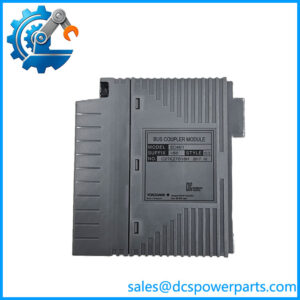
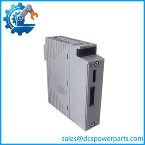
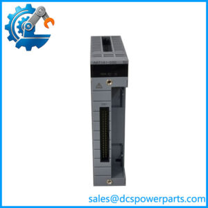
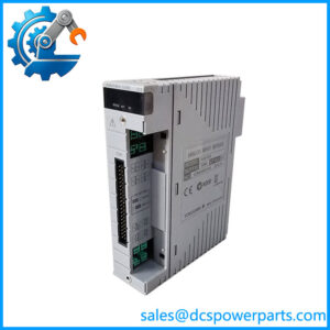
The Yokogawa EC401-10 S2 is an ESB Bus Coupler Module used to establish the communication path between a compatible Field Control Unit and its associated I/O node units. In a distributed control system, this interface carries I/O-related communication between the controller-side hardware and the connected node infrastructure. Its role is therefore different from that of an individual analog input, digital output, or power-supply module.
The family is documented for Yokogawa FIO configurations, including compatible FCU models such as AFV30, AFV40, and specified A2FV50/A2FV70 variants. The module uses the ESB bus interface, with a documented transmission speed of 128 Mbps and a maximum bus distance of 10 m. Yokogawa specifies support for up to nine connectable units, although the practical limit depends on the FCS database and the precise node arrangement.
The coupler also plays a role in system availability. In supported configurations, two coupler modules can be installed to provide a dual-redundant ESB bus arrangement. This requires the correct FCU, slot assignments, companion hardware, and system configuration. Redundancy should not be inferred simply from the presence of a second module.
When sourcing an -10 S2 for maintenance, buyers should pay particular attention to the full suffix and component style. Yokogawa documentation specifies minimum style requirements for certain processor combinations and Sequence of Events Manager applications. A module with the same base model but an incompatible style may not be suitable for the intended installation. Confirming the component tag and existing system configuration before procurement is more reliable than relying on a generic listing description.
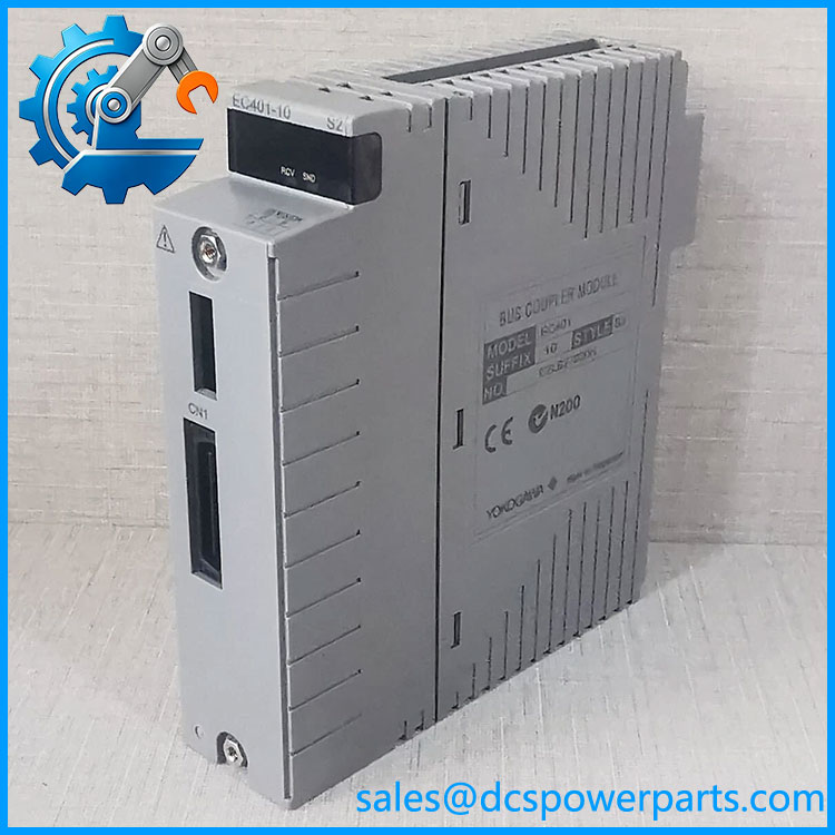
EC401-10 S2
Major Features and Advantages
Dedicated ESB bus communication
The provides the bus interface required by compatible Yokogawa FIO installations. This dedicated function helps maintain the intended communication path between the FCU and its node units. It is a system communication component, not a standalone controller or a general-purpose network adapter.
Support for distributed I/O nodes
The family supports communication with compatible node hardware, including the documented FIO Node Unit arrangements. The number of nodes permitted in a particular installation depends on the system database and supported hardware configuration. Engineering teams should confirm node count and topology before expanding or modifying an existing installation.
Dual-redundant configurations
Yokogawa documents the use of paired modules for supported redundant ESB bus configurations. On applicable FCUs, the couplers occupy the designated slots for the chosen architecture. Slot placement, companion modules, and controller compatibility must be confirmed from the relevant hardware documentation.
Defined transmission characteristics
The documented interface operates at 128 Mbps, with a maximum transmission distance of 10 m for the specified ESB bus connection. These values should not be confused with specifications for optical ESB bus equipment or other communication interfaces in the same control-system family. Cable type and connection method must match the selected bus architecture.
Style-dependent compatibility
The ‘s style designation matters for some system functions. Yokogawa documentation states that only style S3 or later can be combined with the CP471 processor module, while use with Sequence of Events Manager has its own style requirement. These are specific compatibility conditions, not evidence that every application requires the same style. Check the applicable controller and software requirements before approving a replacement.
Maintenance-focused replacement
For an existing installation, replacing a failed coupler with a verified compatible unit can avoid unnecessary changes to the system’s communication architecture. The main procurement task is to establish equivalence in model designation, style, FCU compatibility, bus configuration, and physical condition. A matching base model alone is insufficient evidence of interchangeability.
Applications
The Yokogawa -10 S2 is used in distributed control-system installations where a compatible FCU must communicate with ESB bus node units. Such architectures are common in process-control environments where field signals are collected through distributed I/O hardware and made available to the control system.
In a plant maintenance scenario, the may be held as a critical spare for the FCU communication path. If a coupler develops a fault, maintenance personnel need to determine whether the problem originates in the module, bus cable, node unit, slot connection, or a wider controller issue. Replacing the coupler without checking the communication path and diagnostic indications can leave the original fault unresolved.
The module is also relevant when expanding an established FIO system. Before adding nodes, engineering personnel must check the supported node count, FCS database, cable length, and intended bus topology. Yokogawa documentation gives a maximum connection distance of 10 m for the ‘s documented ESB bus interface. Where longer distances or remote locations are required, the appropriate optical ESB bus equipment and architecture should be evaluated rather than assuming the standard connection can meet the requirement.
For redundant installations, the can form part of a paired bus arrangement. This may support the system’s intended communication availability, but the outcome depends on the complete hardware and configuration. Maintenance teams should verify that both couplers, the processor, node units, and bus cabling match the designed redundancy scheme.
The should not be substituted for an SB401 slave interface or an EB-series bus module. These devices serve different positions or communication functions in their respective architectures. A replacement decision should start with the installed module’s exact designation and the control-system hardware drawing, particularly when an older CENTUM installation is being maintained alongside newer hardware.
Related Products
| Model | Relationship |
|---|---|
| Base ESB Bus Coupler Module family | |
| EC402 | Related ESB bus coupler model; verify port and system requirements |
| SB401 | ESB bus interface slave module used on compatible node-unit hardware |
| EB401 | ER bus master interface module; different function |
| EB501 | ER bus slave interface module; different function |
| AFV30S / AFV30D | Compatible FCU family documented for |
| AFV40S / AFV40D | Compatible FCU family documented for |
| A2FV50S / A2FV50D | Specified FCU family supported by later documentation |
| ANT401 / ANT411 | Optical ESB bus repeater master modules for compatible optical architectures |
These products are related by system architecture, communication function, or documented compatibility. They are not automatically interchangeable.
Installation and Maintenance
Before installing the -10 S2, confirm the installed FCU model, the required style, and whether the system uses a single or dual-redundant bus arrangement. Check the module’s component tag and compare it with the hardware configuration record. For a redundant installation, verify that both couplers and their designated slots meet the applicable configuration requirements.
Follow the site’s approved shutdown, isolation, and electrostatic-discharge procedures before removing or installing the module. Do not disconnect an active communication bus or remove controller hardware unless the maintenance procedure explicitly permits it. Record the original slot assignment and cable routing before removal.
Inspect the module connector, backplane interface, bus cable, and cable connector for damage or contamination. Check that the cable type and length match the installed ESB bus architecture. If a replacement does not restore communication, review node status, diagnostic indications, controller compatibility, and the physical bus path before concluding that the replacement module is defective.
After installation, follow the approved system recovery procedure. Confirm that the FCU recognizes the module, the expected node units are communicating, and relevant I/O diagnostics have returned to the required state. For redundant configurations, complete the prescribed redundancy checks without introducing an unapproved interruption to process control.
Document the replacement part number, style, inspection findings, test results, and any system changes. For older installations, retain the applicable hardware manuals and configuration records with the maintenance documentation. These records help prevent future substitutions based solely on a similar model number.
Product Assurance
Procurement of the Yokogawa -10 S2 should include identification checks and an agreed inspection scope. Request photographs of the complete nameplate, style marking, connector area, and module condition. Compare these details with the removed module and the installed FCU’s compatibility requirements before accepting the part as a replacement.
Technical documentation establishes the family’s role and key interface specifications, but it does not establish the condition or history of a specific unit being offered. New, surplus, refurbished, and used units should be described accurately, with any functional testing stated separately from visual inspection.
Where testing is available, request a record showing what was checked and whether the module was evaluated in a compatible system. Confirm warranty coverage, return conditions, packaging, and expected delivery lead time before committing to a critical-spares purchase.
The final acceptance decision should be based on the exact module designation, style compatibility, physical condition, and documented test evidence. This is especially important when maintaining an established DCS installation, where an incorrect bus coupler can delay fault recovery even if its base model appears correct.