Description
Technical Specifications
| Parameter | Specification |
|---|---|
| Product Model | AAT141-S00 S2 |
| Manufacturer | Yokogawa Electric Corporation |
| Product Type | Isolated TC/mV input module |
| Input Channels | 16 |
| Thermocouple Types | J, K, E, B, R, S, T, N |
| Millivolt Input Ranges | −100 to +150 mV; −20 to +80 mV |
| Maximum Allowable Input Voltage | ±5 V |
| Input-to-System Withstand Voltage | 1,500 V AC for 1 minute |
| Input Resistance | 2 MΩ or greater, powered and unpowered |
| Thermocouple Accuracy | ±30 µV |
| Millivolt Accuracy | ±80 µV on the −100 to +150 mV span; ±30 µV on the −20 to +80 mV span |
| Reference-Junction Compensation Accuracy | Within ±1°C under specified conditions |
| Maximum Signal-Source and Wiring Resistance | 1,000 Ω |
| Data Update Period | 1 second |
| Burnout Detection | Configurable by channel group; up-scale/down-scale behavior depends on configuration |
| Maximum Current Consumption | 450 mA at 5 V DC |
| Approximate Weight | 0.2 kg |
| Connection Accessories | ATT4S/ATT4D terminal blocks, depending on the required connection arrangement |
Specifications are based on published AAT141 family data. Verify the exact suffix, connection accessory, and applicable manual revision before engineering approval.
Product Overview
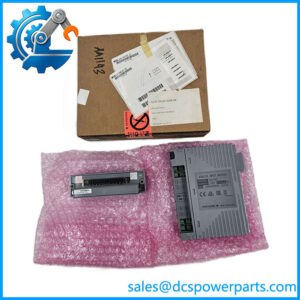
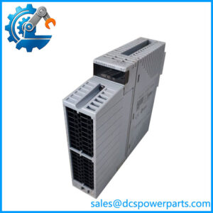
The Yokogawa AAT141-S00 S2 is designed for temperature measurement and low-level voltage acquisition in compatible industrial control systems. It accepts signals from thermocouples and other millivolt-level sources, providing 16 isolated input channels for process monitoring and control. Typical measurement points include reactor temperatures, furnace zones, heat exchangers, process piping, and equipment where thermocouple-based sensing is required.
The module supports thermocouple types J, K, E, B, R, S, T, and N, as well as two specified millivolt input ranges. Each channel must be configured for the appropriate sensor type and measurement range. Thermocouple wiring requires particular care: extension wire, polarity, connector materials, and reference-junction compensation can all affect the measurement. Incorrect thermocouple wiring may produce plausible but inaccurate readings, making a simple signal-presence check insufficient for commissioning.
Published specifications list thermocouple accuracy of ±30 µV and millivolt accuracy of ±80 µV for the −100 to +150 mV span or ±30 µV for the −20 to +80 mV span. Reference-junction compensation accuracy is specified within ±1°C under the stated conditions. These are module-level specifications, not a guarantee of total temperature-system accuracy. Sensor tolerance, extension-wire errors, installation practices, and the selected thermocouple type also influence the final reading.
The module’s documented data update period is one second, so it should be evaluated against the process’s response requirements rather than selected solely by channel count. The AAT141-S00 S2 should also be matched to the installed I/O architecture and the correct thermocouple terminal assembly. Confirm the precise model and suffix before replacement; a similar-looking analog input module may support different signal types or connection hardware.
Major Features and Advantages
Sixteen isolated input channels
The AAT141-S00 S2 consolidates 16 thermocouple or millivolt measurement points in one module. Its isolated-channel design helps reduce unwanted electrical interaction between measurement circuits, subject to the specified hardware arrangement. This is useful in cabinets handling multiple temperature measurements across different parts of a process.
Support for multiple thermocouple types
Support for J, K, E, B, R, S, T, and N thermocouples allows the module to accommodate a range of industrial temperature measurement applications. The sensor type must be configured correctly for each measurement point. Type B thermocouples have specific low-temperature limitations and compensation considerations; consult the manufacturer’s documentation before using them near the lower end of their practical range.
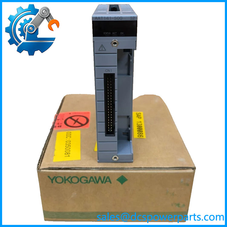
AAT141-S00 S2
Low-level millivolt measurement
The module supports −100 to +150 mV and −20 to +80 mV ranges. These ranges allow it to receive compatible low-level voltage signals without treating it as a general-purpose voltage input module. Confirm the source range and input configuration before connecting a signal source.
Reference-junction compensation
Thermocouple measurements depend on the reference-junction temperature as well as the measuring junction. The published specification gives reference-junction compensation accuracy within ±1°C under specified conditions. Correct terminal hardware and installation practices are essential to realizing that performance; compensation accuracy alone does not define the accuracy of the complete sensor assembly.
Configurable burnout detection
The documented family supports burnout detection with selectable up-scale or down-scale behavior, subject to configuration. This can help the control system distinguish a broken sensor circuit from a normal process measurement. Verify the configured burnout response and associated alarm logic during commissioning instead of assuming that all installations use the same failure indication.
Compatibility with designated Yokogawa I/O hardware
The AAT141 family uses dedicated thermocouple/mV connection accessories, including ATT4S and ATT4D terminal-block arrangements. The correct accessory depends on the wiring design. Confirm the terminal block, cable arrangement, and supported node configuration before ordering a replacement module.
Applications
Process temperature monitoring
The -S00 S2 can collect thermocouple measurements from process vessels, piping, heat exchangers, and other temperature-controlled equipment. The controller can use these measurements for display, trending, alarms, and control strategies. Correct sensor-type configuration and reference-junction compensation are essential when commissioning each point.
Furnaces and thermal processing equipment
Thermocouple types commonly used in industrial heating equipment can be connected where their characteristics fall within the module’s supported inputs. Engineers should verify the selected thermocouple type, expected operating range, sensor protection, and wiring materials. A module’s ability to accept a sensor type does not establish that the complete measurement assembly is suitable for every furnace temperature or atmosphere.
Boilers and heat exchangers
Temperature measurement around boilers, heat exchangers, and associated process equipment helps operators assess thermal performance and identify abnormal operating conditions. The module acquires the sensor signal, while scaling, alarms, and control logic are configured in the wider system. Confirm that the one-second update period meets the application’s monitoring and control requirements.
Equipment temperature supervision
Motors, bearings, skids, and packaged process equipment may use thermocouples to monitor temperature at designated locations. The module can support such measurements when the sensor type, signal range, and installation architecture are compatible. If the application requires a different sensor interface, such as direct RTD measurement, use the appropriate module rather than assuming TC/mV input capability covers all temperature sensors.
Legacy DCS maintenance
For existing Yokogawa installations, the -S00 S2 may be relevant when the installed parts list calls for this specific TC/mV module. Replacement planning should verify the exact suffix, node compatibility, terminal assembly, and configured sensor types. If a proposed replacement has a different model or revision, obtain compatibility confirmation before removing the original module from service.
Related Products
| Model | Relationship |
|---|---|
| Base 16-channel isolated TC/mV input module | |
| AAT145 | Related 16-channel isolated TC/mV input module in the Yokogawa analog I/O family |
| AAR181 | Isolated RTD input module for compatible resistance-temperature detectors |
| AAI143 | 16-channel isolated 4–20 mA analog input module |
| AAI543 | 16-channel isolated 4–20 mA analog output module |
| AAV144 | 16-channel isolated voltage input module |
| ATT4S-00 | Pressure-clamp terminal block for compatible thermocouple/mV connections |
| ATT4D-00 | Dual pressure-clamp terminal block for compatible thermocouple/mV connections |
| ATT4S-10 | Pressure-clamp terminal block with surge absorber |
| ATT4D-10 | Dual pressure-clamp terminal block with surge absorber |
These are related products or connection accessories, not direct substitutes. Confirm the input type, channel count, connection method, and approved system configuration before selecting an alternative.
Installation and Maintenance
Before replac S2, compare the complete nameplate code with the installed parts list and the applicable Yokogawa documentation. Follow site isolation procedures and the manufacturer’s approved module-handling instructions. Do not assume that the S2 designation identifies a particular redundancy capability, revision, or certification without supporting documentation.
Inspect the module contacts, housing, and terminal assembly for damage, contamination, or signs of overheating. Confirm that the installed terminal block and thermocouple wiring arrangement match the approved drawings. Check sensor polarity and ensure that thermocouple extension wire and connectors are appropriate for the sensor type. Avoid introducing ordinary copper wire into a thermocouple circuit where it would create an unintended junction or measurement error.
After installation, verify that the control system recognizes the module and that the correct input type and range are configured for each channel. Use an appropriate calibrated signal source or temperature simulator to test representative points. Where practical, check both the indicated value and the expected response to an open sensor circuit. Confirm burnout behavior, reference-junction compensation, alarm thresholds, and engineering-unit scaling before returning measurements to automatic control.
Document the module identification, terminal configuration, channel test results, and any changes to sensor wiring. If readings differ from the expected values, investigate sensor wiring, reference-junction conditions, and configuration before concluding that the replacement module is defective.
Product Assurance
For procurement of the Yok S2, verify the complete model designation, physical condition, and compatibility with the intended system. The published specifications establish the family-level TC/mV input characteristics but do not prove the condition or service history of a particular unit.
Request a clear nameplate photograph and confirmation of the exact ordering code. Confirm whether the required terminal block or other connection hardware is included or must be purchased separately. If the supplier describes the unit as an upgraded, revised, or replacement version, ask for documentation establishing compatibility with the installed hardware and engineering configuration.
Where functional testing is available, request the test scope and results. Relevant checks may include input response using a calibrated simulator, channel status, reference-junction compensation, and burnout indication. A visual inspection alone cannot demonstrate measurement accuracy across all 16 channels.
Finally, confirm the actual unit’s supplied condition, warranty terms, traceability records, and delivery schedule. For temperature-critical applications, the replacement decision should be based on the exact hardware identity, a suitable connection arrangement, and documented acceptance criteria—not solely on a similar catalog description.