Description
Product Overview
1MRK002311-AAr02 is the medium-range member of the LDCM family inside ABB Relion 670 terminals — the ordering table calls it “Optical medium range LDCM”, and the -AA suffix is what separates it from the multimode short-range -AB and the 1550 nm long-range -BA. It sits in a remote-communication position of a RED670, REG670, REL670, RET670 or REC670 chassis and turns a single-mode fiber pair into the synchronous channel over which two line ends exchange their sampled currents.
The suffix decides the glass. This board drives single-mode 9/125 µm fiber at 1310 nm through FC/PC connectors, with a nominal 22 dB optical budget — enough to cross a valley, a river or a stretch of open country between two substations rather than a compound wall. Where the short-range board stops at a couple of kilometers, 1MRK002311-AAr02 is the point at which a differential scheme stops being a station-level arrangement and becomes a line-level one.
The payload is unchanged across the family and it is what the design must protect: every 5 ms a telegram carries three-phase current samples, the time reference that aligns both terminals, trip and block flags, alarms and eight binary signals for transfer trip or interlocking. On a 70 km route, that cadence means the link has to hold frame alignment and clock relationship across hundreds of thousands of splices-per-year worth of optical path — which is why route loss accounting, connector discipline and power-mode choice matter more here than on any short-haul application.
Technical Specifications
| Parameter | Value |
|---|---|
| Model | 1MRK002311-AAr02 |
| Hardware revision | r02, functionally identical to later revisions of the same type |
| Manufacturer | ABB, Sweden |
| Product type | Optical medium range line data communication module, IED plug-in board |
| Optical interface | FC/PC connector, single-mode pair |
| Fiber type | Single-mode 9/125 µm |
| Wavelength | 1310 nm nominal, 1290 nm minimum |
| Optical budget | 22 dB nominal, including 20 to 30 year aging margin |
| Typical reach | About 60 to 80 km, confirmed by link calculation on the actual route |
| Receiver sensitivity | Approximately −30 dBm |
| Output level | Low and high power modes; high mode adds about 3 dB of launch power |
| Attenuation basis | 0.32 dB/km fiber, 0.3 dB per FC/PC connector, 0.08 dB per factory splice |
| Protocol and framing | IEEE C37.94 synchronous, HDLC |
| Data rate | 64 kbit/s default, 2 Mbit/s mode selectable |
| Telegram payload | Three-phase currents every 5 ms, time reference, trip/block/alarm, eight binary signals |
| Channels per terminal | Up to four remote communication interfaces |
| Power | From the IED backplane, no independent supply |
| Slot positions | P30:5, P30:6, P31:3, P32:2, P32:3 by chassis variant |
| Compliance | IEC 60255-26 EMC, IEC 60255-1 and IEC 60255-27 for the parent IED |
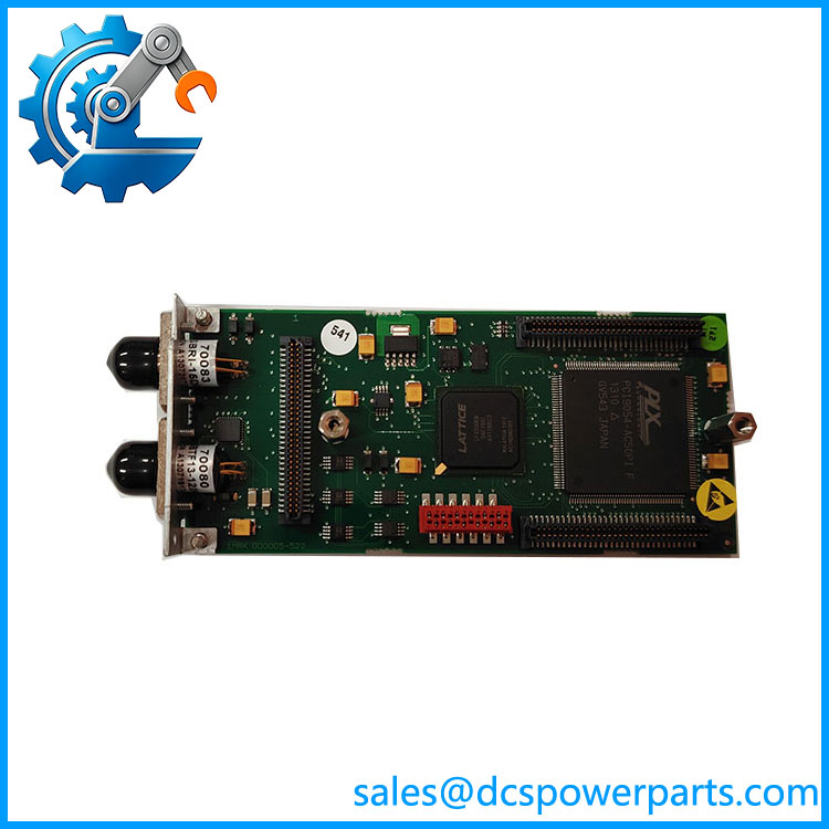
1MRK002311-AAr02
Key Features and Advantages
A 22 dB budget gets spent, not assumed
Twenty-two decibels sounds generous until it is divided by distance. At 0.32 dB/km, a 70 km route consumes roughly 22.4 dB of fiber alone before a single connector is counted — which is precisely why the budget is quoted together with its assumptions of 0.3 dB per FC/PC mating, 0.08 dB per factory splice, and a margin reserved for transmitter and receiver aging over two to three decades. 1MRK002311-AAr02 rewards a route that is calculated this way and exposes one that is estimated.
Single-mode discipline at the connector
On a short multimode hop, a dirty ferrule costs margin. On this board it costs a protection channel: an FC/PC end face with contamination or a badly polished repair splice can consume the entire spare budget of a 65 km link. The FC/PC interface, the 1310 nm window and the 22 dB figure together make connector quality a commissioning measurement rather than an assumption.
Power mode selected for heat as much as for margin
Because medium and long range boards sit in continuous transmission over long paths, the application guidance is to run them at low power to keep dissipation down, reserving the high-power mode — worth about 3 dB — for routes close to their calculated maximum. That is the opposite instinct from a short-haul installation, and getting it right protects both the transceiver lifetime and the cabinet thermal budget.
The middle rung of a three-tier family
With 1MRK002122-AB below it and 1MRK002311-BA above it, this board fills the distance band where multimode is too short and 1550 nm optics are unnecessary. A single chassis can carry all three types in different positions, so one terminal serves a near station pair and a distant one without a second platform.
Applications
Transmission lines between substations that sit tens of kilometers apart are the primary case: a 220 kV or 110 kV feeder whose two ends lie on opposite sides of a river valley, a tie between a generation switchyard and a load center, or a line crossing an industrial belt where no telecom circuit is commercially available. With 1MRK002311-AAr02 in both terminals, the differential function runs on dedicated dark fiber that the utility already owns.
Regional grid ties benefit where the operator wants unit protection independent of the SDH network — the module’s 64 kbit/s channel is small enough to be carried directly, yet the protection does not depend on a multiplexer’s availability. Where such a multiplexer is used, the LDCM still terminates the optical path and the C37.94 framing remains end to end.
Hydro schemes with long valley runs use it between cascaded plants separated by more than the multimode limit, and metro transmission rings apply it between substations on the ring’s perimeter. Binary signal transfer schemes also specify the board when the transfer trip has to reach a station beyond a few kilometers — interlocking, remote trip from external protection, or status exchange across a long line section.
Industrial complexes with widely separated HV nodes — a port area, an integrated steel site with satellite substations, a refinery with an outlying tank farm — use the same board to obtain unit protection across a private single-mode network.
Related Products
1MRK002122-AB — short-range LDCM on multimode 62.5/125 µm with ST connectors and 13 dB budget, about 3 km; the tier below. 1MRK002311-BA — long-range LDCM on single-mode at 1550 nm with 26 dB budget, for 110 to 130 km routes; the tier above. 1MRK005500-AA — Ethernet SFP module with optical LC connector for IEC 61850 station bus traffic. 1MRK005500-BA — Ethernet SFP module with RJ45 connector, the copper station-bus variant. 1MRK002266-EA — optical Ethernet module for station communication on the same IED platform. 1MRK001608-AB / 1MRK001608-BB / 1MRK001608-CB — serial SPA, LON, DNP and IEC 60870-5-103 modules in plastic, plastic-glass and glass versions. 1MRK002309-AA — galvanic RS485 module for short copper links inside a station. 1MRK007002-AA — GPS time module, where the differential function takes its clock from a global reference instead of the channel. 1MRK002282-AB — IRIG-B synchronization module, the alternative external time base. RED670 / REL670 / REG670 — terminals hosting 1MRK002311-AAr02 in line, distance and generator protection.
Installation and Maintenance
Before installation: obtain the route loss from an optical time-domain reflectometer survey rather than from drawings, because the 22 dB budget on 1MRK002311-AAr02 is consumed at roughly 0.32 dB per kilometer and a misjudged span shows up only at the far end. Confirm the chassis offers a remote-communication position at P30:5, P30:6, P31:3, P32:2 or P32:3, and confirm the fiber is single-mode 9/125 µm with FC/PC terminations — multimode patch cords at the distribution panel are a common and silent error. Decide the low or high power mode from the calculated margin, with low preferred unless the route approaches its maximum, then isolate the IED and fit the module.
Maintenance practice: inspect and clean FC/PC ferrules at every mating, and record launch power and received level at each end at commissioning — on a long span these two numbers are the only early warning available before a channel alarm. Re-measure annually and after any work at the fiber panel; a 2 to 3 dB shift is connector or splice degradation. Verify after any board change that one terminal is clock master and the other slave, run a loop-back test, and read the channel supervision counters before the protection is returned. Store spare 1MRK002311-AAr02 units with port caps fitted, revision recorded and within the parent IED’s environmental range.
Warranty and Quality
1MRK002311-AAr02 is delivered as a plug-in module with its revision level printed on the label and repeated in the packing documentation, so the station knows which build occupies which position. Each unit passes a single-mode loop-back verification covering launch power, received level, frame lock and channel status, and the measurement record accompanies the shipment. A 12-month warranty applies under standard substation-automation practice, with repair or replacement for quality-related failure. Because medium-range schemes usually involve two terminals hundreds of kilometers apart, sets are checked for revision consistency before dispatch, and support covers slot assignment, clock role configuration, budget review from OTDR data and the low or high power decision.