Description
Product Overview
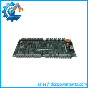
1MRK002122-ABr07 is a revision-07 build of the short-range optical line data communication module that ABB fits inside Relion 670 terminals under the catalogue name “Optical short range LDCM” and the factory marking 670LDCM02 SHORT. The -AB suffix fixes it to multimode glass and a few kilometers of reach; the r07 marking identifies the build level, not a change in capability. Physically it is a plug-in card occupying one remote-communication position in a RED670, REG670, REL670, RET670 or REC670 chassis.
What the card does is narrow and unforgiving. Between the two ends of a protected line it carries a telegram every 5 ms containing three-phase current samples, the time reference that keeps the terminals in step, trip and block indications, alarms and eight binary signals available for interlocking or transfer trip. Frame continuity and clock relationship are therefore part of the protection performance, and the card is treated in the documentation as protection hardware rather than as a data interface.
Practical deployment is bounded by optics. Graded-index 62.5/125 µm fiber gives the module 13 dB of budget and about 3 km of working distance; 50/125 µm gives 9 dB and roughly 2 km. Launch power starts at −17 dBm and receiver sensitivity sits at −30 dBm, with a high-power setting adding around 3 dB. Read together with the standard loss assumptions — 3 dB/km in the glass, 1.5 dB per ST mating, 0.5 dB per repair splice and a small aging allowance — those numbers decide whether a proposed station pair can be closed with multimode at all.
Technical Specifications
表格
| Parameter | Value |
|---|---|
| Model | 1MRK002122-ABr07 |
| Hardware revision | r07, specification unchanged across r03, r05 and r09 |
| Manufacturer | ABB, Sweden |
| Product type | Line data communication module, optical short range, IED plug-in board |
| Optical connector | ST duplex, transmit and receive pair |
| Fiber | Graded-index multimode 62.5/125 µm as standard; 50/125 µm supported |
| Wavelength | 820 nm peak emission, 865 nm nominal, 792 nm minimum |
| Optical budget | 13 dB on 62.5/125 µm, 9 dB on 50/125 µm |
| Working distance | Approximately 3 km and 2 km, established by link calculation |
| Launch and sensitivity | −17 dBm minimum output on 62.5/125 µm; −30 dBm receiver sensitivity |
| Protocol | IEEE C37.94 synchronous with HDLC framing |
| Data rate | 64 kbit/s default, 2 Mbit/s mode selectable |
| Telegram payload | Three-phase currents every 5 ms, time reference, trip/block/alarm, eight binary signals |
| Channels per terminal | Up to four remote communication interfaces |
| Supply | From the IED backplane, no external power connection |
| Slot positions | P30:5, P30:6, P31:3, P32:2, P32:3 according to chassis variant |
| Compliance | IEC 60255-26 EMC, IEC 60255-1 and IEC 60255-27 for the parent IED |
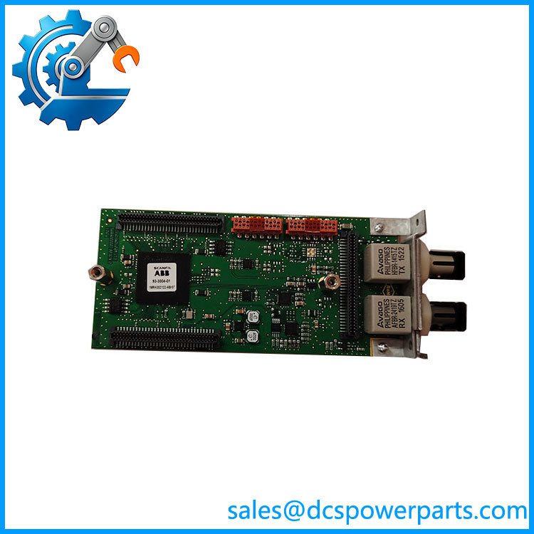
1MRK002122-ABr07
Key Features and Advantages
Acceptance is a measurement, not a configuration step
Nothing about 1MRK002122-ABr07 can be proven from a settings file. Launch power, received level, frame lock and the supervision counters are the four readings that decide whether a channel is healthy, and all four are obtainable at commissioning with an optical power meter and the terminal’s own diagnostics. That gives an engineer a baseline to compare against next year, instead of a channel that is assumed good until it misoperates.
One fiber pair serving two protection duties
Eight binary signals share the telegram with the currents, so transfer trip, interlocking and status exchange do not need a second communication path, a second pair of fibers or a second set of terminations in the fiber panel. On a station pair where trench capacity and panel ports are already committed, that consolidation is the difference between a feasible scheme and a re-cabling project.
A budget that has to survive the plant, not the test
The 13 dB figure includes an allowance for transmitter and receiver aging over two to three decades of service. Connector loss and splice loss are accounted separately precisely so that the residue stays available after twenty years of maintenance activity. 1MRK002122-ABr07 is therefore specified against a calculated budget and a measured survey, and a link that passes on a bench with a two-metre patch cord proves nothing about that.
Revision traceability inside a mixed fleet
Terminals installed over more than a decade rarely carry uniform builds, and the r07 marking is the only durable record of what went into a position. Keeping it in the asset file makes a later repeat-failure investigation readable, and it prevents a spare of a different build from being assumed identical when the maintenance history is reconstructed years afterwards.
Applications
Compound-internal station pairs are the standard deployment: a 220 kV yard and its 110 kV counterpart sharing a fence, a generation switchyard and the adjacent grid node, or two bays protecting a short interconnecting feeder. Distance is trivial, protection duty is not, and 1MRK002122-ABr07 closes the differential loop on multimode glass already present in the cable trench.
Captive power plants attached to industrial sites use it to tie the plant substation to the utility interface a kilometer or two away — a paper mill, a cement works, an aluminium smelter or a refinery each present this topology, and each needs unit protection rather than backup overcurrent. Cascade hydro stations along the same river reach apply the same approach between successive REG670 terminals.
Metro and urban cable networks use the board between neighboring distribution substations, where the physical run is short and an uncleared fault converts directly into interrupted supply. Schemes that carry only binary signals also specify it: busbar-to-line interlocking, transfer trip from external protection, or status exchange for a sequential black-start, all on the supervised pair.
Panel builders and test departments keep a module back to back on the bench, connecting two terminals over a short patch cord to prove the differential function end to end before a scheme is energized.
Related Products
1MRK002311-AA — medium range LDCM on single-mode 9/125 µm at 1310 nm with FC/PC connectors and 22 dB budget, covering roughly 60 to 80 km; the distance tier above this board. 1MRK002311-BA — long range LDCM at 1550 nm with 26 dB budget for 110 to 130 km routes. 1MRK005500-AA — Ethernet SFP module, optical LC connector, for IEC 61850 station bus traffic. 1MRK005500-BA — Ethernet SFP module, RJ45 connector, the copper station-bus alternative. 1MRK002266-EA — optical Ethernet module for station communication on the same IED platform. 1MRK001608-AB / 1MRK001608-BB / 1MRK001608-CB — serial modules for SPA, LON, DNP and IEC 60870-5-103 in plastic, plastic-glass and glass versions. 1MRK002309-AA — galvanic RS485 module for short copper links within a station. 1MRK007002-AA — GPS time module, used where the differential function is clocked from a global reference rather than the channel. 1MRK002282-AB — IRIG-B synchronization module, the alternative external time base. RED670 / REL670 / RET670 — terminals that host 1MRK002122-ABr07 in line differential and distance protection schemes.
Installation and Maintenance
Before installation: settle the position first. The chassis slot map differs between case variants, so a free opening is not automatically a remote-communication opening at P30:5, P30:6, P31:3, P32:2 or P32:3. Then count channels against the scheme — one for a two-ended line, two per end for a three-ended line, a main and standby pair for redundancy. Survey the route with an optical time-domain reflectometer, compare the measured loss with the 13 dB budget, and set the optical power level from the remaining margin: low for runs up to about 1 km, high beyond. Isolate the IED before fitting 1MRK002122-ABr07, and match patch cords to the installed glass.
Maintenance practice: clean ST ferrules before each mating and after any work at the distribution frame, since one contaminated end face can consume more budget than the entire aging allowance. Write the commissioning readings into the station record — launch power, received level and the date — then repeat the measurement annually; a 2 to 3 dB drop is connector wear, not a failing card. After any board substitution, restore the channel configuration, confirm master and slave clock roles at the two ends, run a loop-back test and read the supervision counters before the protection is released. Keep spare 1MRK002122-ABr07 units capped, labeled by revision and stored within the parent terminal’s environmental limits.
Warranty and Quality
1MRK002122-ABr07 ships as a plug-in module whose revision level appears on the label and again in the packing documentation, so a station receives the build it ordered rather than an interchangeable-looking substitute. Each unit is verified on a fiber loop-back bench for launch power, received level, frame lock and channel status, and the measurement sheet accompanies the delivery. A 12-month warranty applies under standard substation-automation practice, covering repair or replacement of quality-related failures. Where a scheme depends on several modules, sets are checked for revision consistency before dispatch, and technical support covers slot assignment, clock role configuration, budget review from survey data and the choice between low and high optical power settings.