Description
Technical Specifications
| Parameter | Specification |
|---|---|
| Product Model | AAI143-S50 |
| Manufacturer | Yokogawa |
| Product Type | Analog input module |
| Input Channels | 16, isolated |
| Input Signal | 4–20 mA DC |
| Allowable Input Current | 24 mA |
| Input Resistance, Power On | 270 Ω at 20 mA to 350 Ω at 4 mA |
| Input Resistance, Power Off | 500 kΩ or greater |
| Measurement Accuracy | ±16 µA |
| Data Update Period | 10 ms |
| Transmitter Supply | 19.0 V minimum at 20 mA |
| Maximum Transmitter Supply | 25.5 V at 0 mA |
| Transmitter Current Limit | 25 mA |
| Transmitter Configuration | Individually selectable 2-wire or 4-wire |
| Input-to-System Isolation | 1500 V AC for one minute |
| Temperature Drift | ±16 µA per 10°C |
| Current Consumption | 230 mA at 5 V DC; 540 mA at 24 V DC |
| Weight | Approximately 0.3 kg |
| External Connection | Pressure-clamp terminal, MIL connector cable, or dedicated KS1 cable |
| Redundancy | Dual-redundant configuration supported |
| Explosion Protection | Not included in the S50 configuration |
Specifications are based primarily on Yokogawa’s AAI143 general specification documentation. The S50 suffix identifies the standard, non-explosion-protected, basic configuration.
Product Introduction
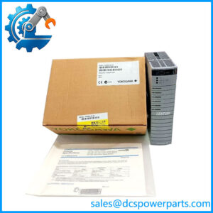
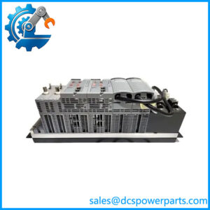
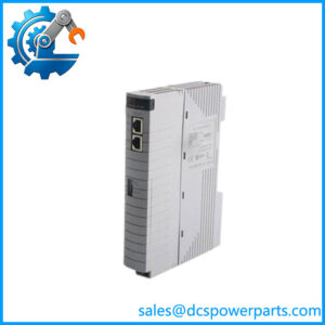
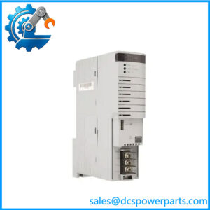
Yokogawa AAI143-S50 Analog Input Module
The Yokogawa AAI143-S50 provides 16 isolated current-input channels for acquiring 4–20 mA signals from industrial transmitters. Each channel can be configured for 2-wire or 4-wire transmitter operation, allowing the module to support different field instrument wiring arrangements within a CENTUM control-system installation.
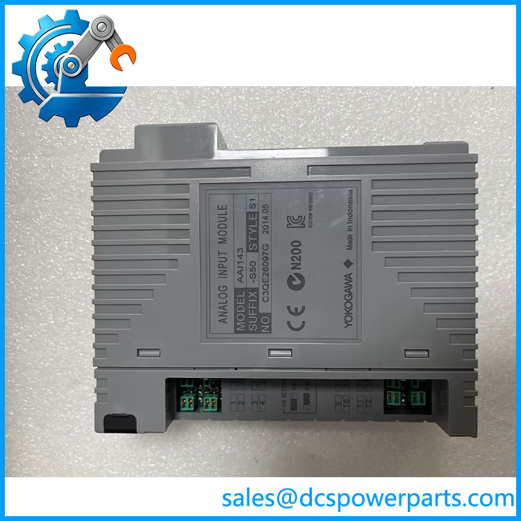
AAI143-S50
Its 10 ms data update period and ±16 µA specified accuracy support continuous process measurement. Input-to-system isolation helps protect the control-system side from electrical disturbances originating in field wiring. Dual-redundant configuration support is also available when the surrounding I/O architecture is designed accordingly.
Application Scenarios & Field Pitfalls
The AAI143-S50 is appropriate for process installations where multiple current-loop transmitters must be monitored through a centralized DCS. Common commissioning problems include incorrect transmitter wiring, unsuitable loop voltage, mismatched channel configuration, and termination hardware differences. These issues can produce inaccurate readings, unstable measurements, or complete channel failure even when the replacement module itself is functional.
Typical applications
- Pressure measurement: Acquires 4–20 mA signals from pressure transmitters installed on process pipelines and vessels.
- Flow monitoring: Collects analog outputs from compatible flow transmitters and flow measurement instruments.
- Level control: Receives level transmitter signals for tank and vessel monitoring.
- Chemical and power plants: Integrates multiple field measurement loops into CENTUM CS or CENTUM VP control systems.
Engineering checks before installation
- Verify the input signal type. The AAI143-S50 is a 4–20 mA current input module. Do not substitute a voltage-input or thermocouple-input module based only on channel count.
- Check 2-wire and 4-wire configuration. Each channel has a setting for transmitter wiring. Confirm the setting against the actual field instrument before energizing the loop.
- Calculate transmitter voltage margin. The module provides at least 19.0 V at 20 mA for 2-wire transmitters. Include cable resistance, transmitter minimum operating voltage, and any additional loop devices in the voltage calculation.
- Confirm the isolation arrangement. The specified 1500 V AC withstand rating applies between the input and system circuits under the documented test conditions. It does not automatically establish hazardous-area certification.
- Check the termination hardware. Pressure-clamp terminals, MIL connector cables, and dedicated KS1 cables have different connection arrangements. Verify the installed interface before ordering a complete replacement.
- Validate redundancy configuration. Although the module supports dual-redundant operation, the rack, controller, wiring, and system configuration must also support the intended arrangement.
- Check HART requirements. The S50 version is not the HART-designated H variant. If digital HART communication is required, verify the appropriate module suffix and system firmware requirements.
These checks are based on Yokogawa’s published electrical and installation specifications.
Related Products
| Model | Function Difference | Potential Application |
|---|---|---|
| AAI543-H50 | HART-capable version of the 16-channel current input module | Smart transmitter integration |
| AAI543-S53 | Standard input version with extended environmental configuration | Installations requiring wider temperature capability |
| AAI543-H53 | HART version with extended environmental configuration | Smart instrument monitoring in wider temperature conditions |
| AAI141-S50 | Related analog input module with a different input configuration | Alternative analog measurement requirements |
| AAI135-S50 | Eight-channel isolated current input module | Lower-density 4–20 mA acquisition |
| AAI135-H50 | Eight-channel current input module with HART support | HART-enabled transmitter acquisition |
| AAI543-S50 | Analog current output module | Sending 4–20 mA control signals to field devices |
| AAI835-S50 | Combined analog input/output module | Applications requiring both current input and output channels |
These modules belong to related Yokogawa analog I/O families, but they differ in channel count, signal direction, and communication functions. They should not be treated as direct substitutes without checking the system configuration.
Procurement note: When ordering the -S50, confirm the complete suffix and terminal configuration. In particular, distinguish the base module from /A4S00 and other connection-option variants. For replacement work, compare the installed module label, rack type, cable arrangement, channel settings, and redundancy configuration before approving installation.