Description
Product Overview
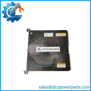
The Woodward 9905-972 is a six-channel analog output module in the legacy LINKnet distributed I/O family. It generates six independent 4–20 mA current-loop signals for compatible field equipment. In a turbine or engine control installation, these outputs may be used for analog command interfaces such as valve position control, actuator references, or other devices that accept a current-loop setpoint. The exact field application depends on the controller configuration and connected equipment. This module is an output device; it must not be confused with the 9905-968 or 9905-969, which are six-channel analog input modules. Woodward documentation identifies the 9905-972 specifically as a six-channel 4–20 mA output node.
The 9905-972 operates within the LON-based LINKnet architecture. Woodward’s 723PLUS documentation lists it as the six-channel 4–20 mA output node at network address 9 in the documented configuration. The same manual describes the LINKnet network as supporting distributed I/O modules that communicate with the controller through the LON data channel. That address assignment is configuration-specific; it should not be applied automatically to every Woodward installation. The module’s output wiring diagram identifies six channel groups, each with positive, negative, and shield terminals, along with 24 VDC supply and LINKnet communication connections.
For maintenance teams, the Woodward 9905-972 presents two separate compatibility checks: analog output requirements and network configuration. The field device must accept the required 4–20 mA signal, while the controller must recognize the module at the configured LINKnet node address. Woodward later replaced the LON-based LINKnet architecture with CANopen-based LINKnet HT hardware. That transition involves hardware and software changes, so a newer LINKnet HT module should not be treated as a direct plug-in replacement.
Product Introduction
A turbine control system can lose an important command signal when an analog output channel fails, even if the controller itself continues running normally. Troubleshooting must separate the controller’s requested output, the LINKnet communication path, the module’s output stage, and the field wiring.
The Woodward 9905-972 provides six 4–20 mA output channels for legacy LINKnet installations. Before replacement, confirm the output channel assignments, network address, field wiring, and connected device requirements. Its obsolete status also makes revision and functional test evidence important procurement criteria.
Key Technical Specifications
| Parameter | Specification |
|---|---|
| Product model | 9905-972 |
| Manufacturer | Woodward |
| Product family | LINKnet |
| Product type | Analog output module |
| Number of channels | 6 |
| Output signal | 4–20 mA |
| Resolution | 12-bit, reported; verify against applicable manual revision |
| Output monitoring | Internal output-current feedback is described in available technical information |
| Network architecture | LON-based LINKnet |
| Documented 723PLUS network address | 9 |
| Supply voltage | 24 VDC shown in the wiring diagram |
| Power consumption | Approximately 6.0 W at 24 V, reported in product-specific technical information |
| Channel wiring | Positive, negative, and shield terminals per channel |
| Communication terminals | LINKnet communication connection |
| Working temperature | Depends on the installed control-system environment; confirm the applicable manual |
| Protection rating | Not confirmed |
| Lifecycle status | Obsolete / non-preferred for new systems |
The 24 VDC wiring reference and terminal arrangement are shown in Woodward Manual 02882. The network address 9 is listed in the documented 723PLUS configuration. Do not assume that address is universal across all LINKnet installations.
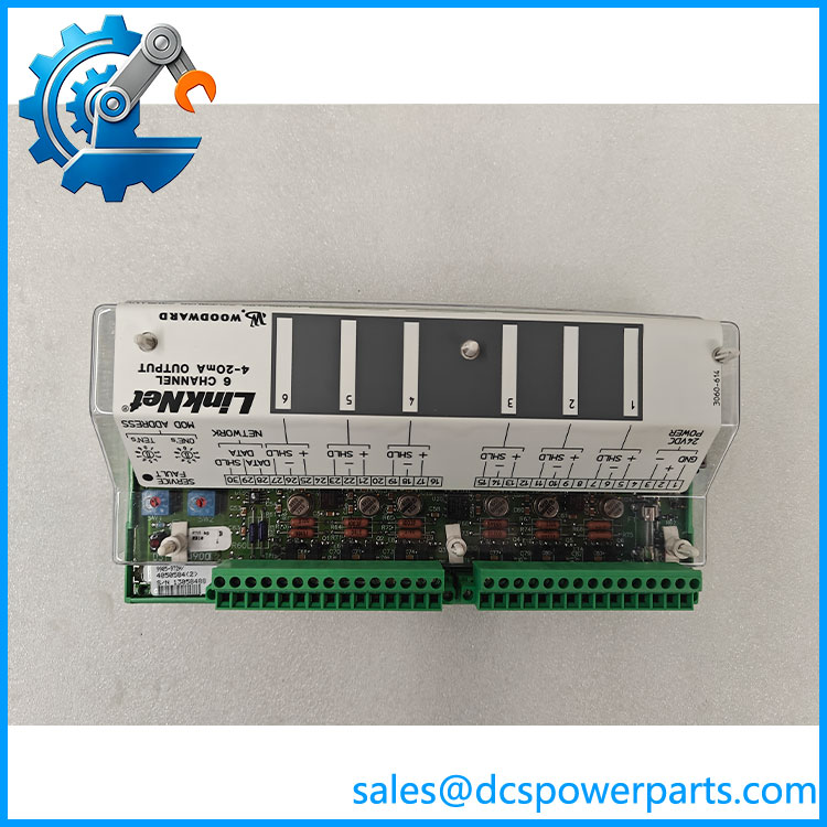
9905-972
Related Products
| Model | Product identification | Engineering relationship |
|---|---|---|
| 9905-968 | Six-channel 4–20 mA analog input, without loop power | Input counterpart; not interchangeable with the 9905-972. |
| 9905-969 | Six-channel 4–20 mA analog input, with 24 V loop power | Input module with a different signal direction and loop-power arrangement. |
| 9905-970 | Six-channel 100 Ω RTD input | Temperature measurement module in the same LINKnet family. |
| 9905-966 | Six-channel thermocouple input, fail-high | Thermocouple input node. |
| 9905-967 | Six-channel thermocouple input, fail-low | Related thermocouple input variant. |
| 9905-971 | 16-channel 24 VDC discrete input | Discrete input node in the same legacy network family. |
| 9905-973 | Eight-channel relay output | Discrete output counterpart, not an analog replacement. |
| 9905-760 | LINKnet termination resistor | Related network component; verify the network termination arrangement. |
| 8200-1202 | LINKnet HT 4–20 mA module, 8 inputs / 2 outputs | Newer CANopen-based hardware; requires system-level migration assessment. |
Frequently Asked Questions
Q1: What is the primary function of the Woodward 9905-972?
It provides six 4–20 mA analog output channels within a Woodward LINKnet distributed I/O system. The controller sends output commands through the network, and the module generates the corresponding current-loop signals for connected equipment.
Q2: Is the 9905-972 an analog input or analog output module?
It is an analog output module. The 9905-968 and 9905-969 are the related 4–20 mA input models. Confusing input and output modules can result in an incorrect spare-part selection and an incompatible signal path.
Q3: How many output channels does the 9905-972 provide?
It provides six independent 4–20 mA output channels. Each channel has positive, negative, and shield connections in the wiring diagram. Verify the terminal assignments against the applicable Woodward drawing before reconnecting field wiring.
Q4: What LINKnet address does the 9905-972 use?
Woodward’s 723PLUS documentation assigns the 4–20 mA output node network address 9. This is a documented system configuration, not a universal setting for every controller. Record the existing node settings before replacing the module.
Q5: Can I hot-swap the 9905-972 while the control system is running?
Do not assume hot-swap permission from the module designation alone. The maintenance procedure depends on the controller architecture and the specific LINKnet installation. Confirm the applicable Woodward manual and plant operating procedure before disconnecting the node or its field wiring.
Q6: Does the 9905-972 support firmware v3.1?
A specific firmware v3.1 compatibility claim cannot be established from the part number. Check the controller software, LINKnet configuration, and module documentation as a complete system. The module’s network and application configuration are more relevant than an isolated firmware-version assumption.
Q7: Can a LINKnet HT module replace the 9905-972 directly?
No direct substitution should be assumed. Woodward identifies LINKnet HT as a CANopen-based updated architecture, whereas the 9905-972 belongs to the older LON-based LINKnet family. Woodward’s obsolescence notice explicitly states that the updated architecture requires hardware and software changes.
Procurement and Maintenance Considerations
Woodward’s obsolescence documentation identifies the 9905-972 as part of the discontinued LON-based LINKnet product family. A later product change notice advised customers that final production and inventory clearance would end beginning in January 2024. This makes the part a legacy spare rather than a current-production module.
For replacement procurement, verify:
- Exact part number and hardware revision.
- Six-channel 4–20 mA output function.
- LINKnet network configuration and node address.
- 24 VDC supply connections and terminal assignments.
- Condition of the PCB, terminals, connectors, and housing.
- Functional test results for all six output channels, including current measurement at representative points across the operating range.
A seller’s statement that a unit powers up is not equivalent to a six-channel output test. Request channel-by-channel test evidence, especially when the module is intended for turbine control or another application where an incorrect analog command can affect equipment operation.