Description
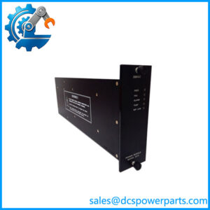
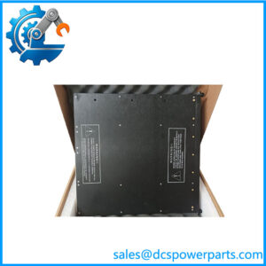
Triconex 3481S2 Analog Output Module
Product Overview
The Triconex 3481S2 is a four-point TMR analog output module used in Tri-GP safety and control systems. Its primary job is to convert controller commands into controlled analog current signals for field equipment such as valve positioners, actuators, and other current-loop devices. The published Tri-GP technical guide specifies four commoned-return, DC-coupled outputs, with a controlled 4–20 mA range and an over-range capability extending to 0–22 mA. The outputs are not individually isolated.
At the module level, the Triconex 3481S2 uses a 12-bit conversion architecture and TMR processing with Forced-Switch Diagnostic (FSD). External loop power is reverse-voltage protected and is specified at 24 VDC nominal, with 32 VDC maximum. The documented load requirements are important: depending on available field voltage, the specified load can extend to 300 Ω at more than 16 VDC, 500 Ω above 20 VDC, 700 Ω above 24 VDC, and 800 Ω above 28 VDC, with the specified minimum supply-current condition.
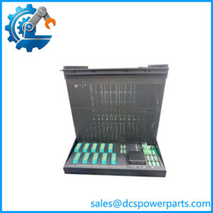
This is a Tri-GP I/O component, not a general-purpose PLC analog-output card. The standard installation uses the 2481S2 analog-output baseplate, while 2483S2 and 2483AS2 baseplates add HART communication capability through the Triconex 4850 HART Multiplexer. The 3481S2 can also be used with the AO external-termination arrangement for hazardous-location applications.
For a legacy installation, replacement should therefore be checked against the complete I/O architecture. Matching the 3481S2 model number alone does not confirm the correct baseplate, termination arrangement, loop-power configuration, or HART requirements.
Product Introduction
Four analog outputs are available from a single Tri-GP module, with 4–20 mA as the controlled operating range and 12-bit resolution. That makes the 3481S2 suitable for continuous final-element commands where a discrete output would be inadequate.
For legacy replacement work, the baseplate is just as important as the module. The documented 2481S2 provides the normal AO interface, while the 2483S2 and 2483AS2 versions integrate HART communication hardware. Those are different installation configurations, not interchangeable pieces of mounting hardware.
Key Technical Specifications
| Parameter | Value |
|---|---|
| Product Model | 3481S2 |
| Manufacturer / Brand | Triconex / Invensys |
| Product Series | Tri-GP |
| Product Type | Analog Output Module |
| Number of Points | 4 |
| Point Configuration | Commoned-return, DC-coupled |
| Isolated Points | None |
| Output Signal | 4–20 mA controlled |
| Over-Range | 0–22 mA |
| Low Output Capability | 0 mA output capability; step function <2 mA |
| Output Accuracy | <0.25% of FSR over 4–20 mA / 0–22 mA |
| Accuracy Temperature Range | 0°C to 70°C (32°F to 158°F) |
| Architecture | TMR |
| Resolution | 12 bits |
| Diagnostic | Forced-Switch Diagnostic (FSD) |
| External Loop Power | 24 VDC nominal; 32 VDC maximum |
| Reverse Voltage Protection | Yes |
| Load at >16 VDC | 300 Ω |
| Load at >20 VDC | 500 Ω |
| Load at >24 VDC | 700 Ω |
| Load at >28 VDC | 800 Ω |
| Over-Range Protection | 36 VDC continuous |
| Negative Voltage Protection | 0 VDC continuous |
| Switch Time on Leg Failure | 1 ms typical; 3 ms maximum |
| Standard AO Baseplate | 2481S2 |
| HART Baseplates | 2483S2 / 2483AS2 |
| Hazardous-Location ETP | 9863-610F with applicable external-termination baseplate |
The specifications above are drawn primarily from the Tri-GP technical product guide and planning/installation documentation.
Major Features / Practical Advantages
Four-point TMR analog output
The 3481S2 provides four analog output points within the Tri-GP architecture. Its TMR design is intended to maintain output-control integrity through redundant processing paths and voting rather than relying on a single electronic path. The technical documentation identifies the module explicitly as Type TMR.
That distinction matters when comparing it with a conventional four-channel PLC AO card. The 3481S2 belongs to a safety-system I/O architecture with specific baseplate, field-power, termination, and diagnostic arrangements.
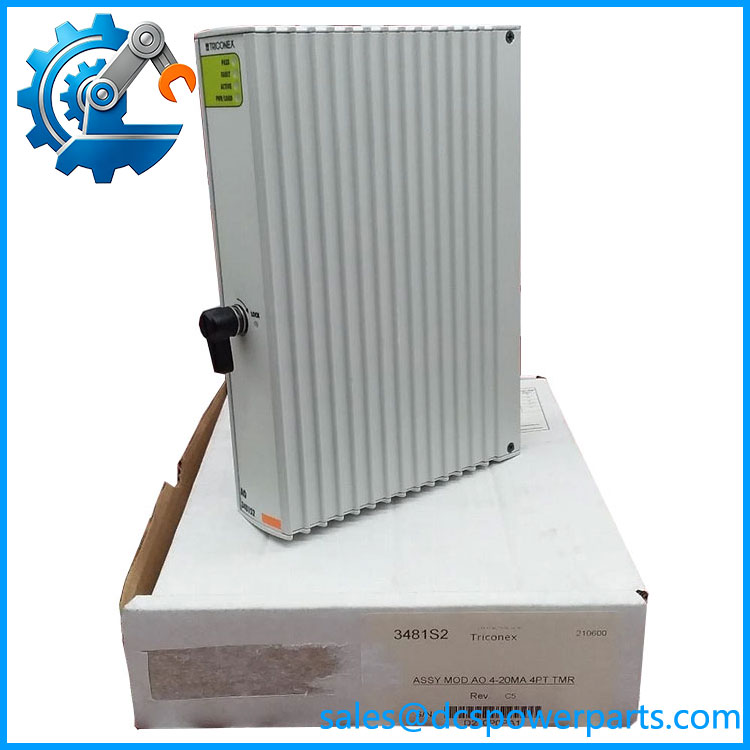
3481S2
Controlled 4–20 mA output
The normal controlled range is 4–20 mA, while the documented over-range capability extends to 0–22 mA. The module also has a 0 mA output capability for a step function below 2 mA. This provides the output range needed for common current-loop final elements while retaining diagnostic and system-control functions.
12-bit resolution
A 12-bit converter provides 4,096 nominal digital levels across the conversion range. That is adequate for many valve-position and continuous-control applications, although the actual process-control precision depends on the complete loop, including the field device, wiring, power supply, calibration, and process measurement.
Forced-Switch Diagnostic
FSD is the documented diagnostic method for the 3481S2. It is part of the module’s fault-detection architecture and should not be confused with a generic PLC channel diagnostic. The module also specifies a rapid switch response following a leg failure: 1 ms typical and 3 ms maximum.
External loop power
The output loop requires external field power. The documentation specifies 24 VDC nominal and 32 VDC maximum, with reverse-voltage protection. This means the field power supply and available voltage at the load have to be included in the replacement calculation.
Load capability depends on field voltage
This is one of the practical details worth checking before replacement. The specified load increases with available field voltage: 300 Ω above 16 VDC, 500 Ω above 20 VDC, 700 Ω above 24 VDC, and 800 Ω above 28 VDC. Long cables, barriers, isolators, and valve positioners can consume part of that available voltage.
HART-compatible installation options
The 3481S2 can be installed with the 2483S2 HART baseplate, where the Triconex 4850 HART Multiplexer provides communication with HART field devices and configuration/asset-management software. The 2483AS2 provides the corresponding hazardous-location configuration.
The important point is that HART functionality comes from the baseplate/multiplexer arrangement, not from assuming that every standalone 3481S2 installation is automatically a HART interface.
Hazardous-location termination option
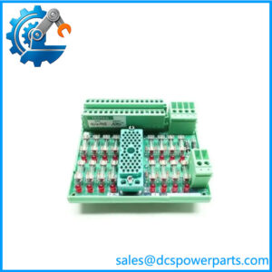
Tri-GP documentation identifies the 9863-610F external termination panel as compatible with the 3481S2 for specified hazardous-location applications. The panel provides energy-limited field connections when installed through the appropriate external-termination architecture. The published guide identifies Zone 2 and Class I, Division 2 applications for this termination arrangement.
Related Products
- 3482S2 — High-current analog output module. It provides four commoned-return outputs with a 4–40 mA controlled range and higher current/load capability than the 3481S2.
- 2481S2 — Standard analog-output baseplate for the 3481S2 and 3482S2. This is the normal baseplate configuration for conventional Tri-GP AO installations.
- 2483S2 — HART analog-output baseplate specifically designed for the 3481S2. It supports the Triconex 4850 HART Multiplexer.
- 2483AS2 — Hazardous-location HART baseplate for the 3481S2. It adds the applicable hazardous-location interface arrangement.
- 5481-1S2 — Analog Output TriPak containing one 3481S2 module and one 2481S2 AO baseplate.
- 5482-1S2 — High-current analog-output TriPak based on the 3482S2. Its output range and load capability differ from the 3481S2.
- 5483S2 — HART Analog Output TriPak using a 3481S2, 2483S2, and Triconex 4850 HART Multiplexer.
- 5483AS2 — Hazardous-location HART Analog Output TriPak using the 3481S2, 2483AS2, and 4850 HART Multiplexer.
- 3351S2 — Tri-GP analog input module. It handles input-side process signals rather than generating 4–20 mA output commands.
- 3451S2 — Tri-GP solid-state relay output module. It is a discrete output device and should not be confused with the 3481S2 analog-current output.
FAQ
Can I replace a 3481S2 with a 3482S2?
Not automatically. Both are Tri-GP analog-output modules, but the 3482S2 is the high-current version. The 3481S2 provides controlled 4–20 mA output with 0–22 mA over-range, while the 3482S2 is specified for 4–40 mA and has different load requirements. Check the configured field load and baseplate arrangement before substituting one for the other.
Can I hot-swap the 3481S2?
The Tri-GP technical guide states that AO modules support a hot-spare module and are mechanically keyed to prevent improper installation in a configured baseplate. That supports maintenance strategies involving spare modules, but it should not be interpreted as permission to remove a live module under every site condition. Follow the approved maintenance procedure for the installed Tri-GP system.
Does the 3481S2 provide isolated analog outputs?
No. The published specification explicitly identifies the four outputs as commoned-return, DC-coupled, with no isolated points. This is a critical distinction when checking an existing field termination design.
What is the maximum output range?
The controlled output range is 4–20 mA, with documented over-range operation to 0–22 mA. Do not describe it as a 0–10 V analog-output module; the Tri-GP documentation specifies a current-output interface.
Does the 3481S2 support HART?
The module can be used in a HART configuration, but HART capability comes from the appropriate 2483S2 or 2483AS2 HART baseplate and Triconex 4850 HART Multiplexer arrangement. A standalone 3481S2 should not be assumed to provide direct HART communication.
Does the 3481S2 support firmware v3.1?
The model number alone does not establish a particular firmware revision. Firmware and system compatibility should be checked against the installed Tri-GP controller generation and project configuration rather than inferred from the 3481S2 part number.
What field power does the 3481S2 require?
The documented external loop power is 24 VDC nominal, with 32 VDC maximum and reverse-voltage protection. Available field voltage also affects the maximum specified load, so the power-supply voltage at the module and at the field device should both be considered.
Is the 3481S2 a SIL 3 device by itself?
It should not be marketed or engineered as an independent safety function simply because it is part of a TMR safety-system architecture. Safety integrity depends on the complete certified system architecture, configuration, application, field devices, diagnostics, and lifecycle controls. The technical guide establishes the module as a TMR Tri-GP AO component; a standalone module-level SIL claim should not be inferred from that fact.
Procurement Note
For a Triconex 3481S2 replacement, verify the complete installation rather than matching only “3481S2.” The most important checks are the four-channel commoned-return configuration, 4–20 mA load requirements, external 24 VDC loop supply, installed baseplate, termination method, and whether the system uses HART communication.
The standard pairing is the 2481S2 analog-output baseplate. If the installation uses HART, check for the 2483S2 or 2483AS2 arrangement and the Triconex 4850 HART Multiplexer. For hazardous-location installations, verify the external-termination architecture and field-energy limitations rather than treating a standard AO baseplate as equivalent.
The published lifecycle documentation identifies 3481S2 as a Tri-GP 4–20 mA, four-point TMR analog-output assembly. It should therefore be treated as legacy Triconex hardware during procurement, with exact hardware markings, physical condition, and configuration compatibility verified before installation.
For surplus or refurbished inventory, request clear photographs of the actual module label, connector condition, keying arrangement, and circuit-board condition where inspection is permitted. A visually correct module can still be the wrong hardware revision or unsuitable for the installed baseplate configuration.