Description
ABB RLM02 3BSE091723R1 PROFIBUS Redundancy Link Module
Product Overview
The ABB RLM02 3BSE091723R1 is a PROFIBUS Redundancy Link Module designed to introduce cable-line redundancy into PROFIBUS DP/FMS networks without requiring every field device to have dual PROFIBUS interfaces. ABB describes the RLM02 as a module that converts a non-redundant PROFIBUS line into two redundant RS-485 lines, or converts redundant A/B lines back into a single PROFIBUS line. This makes it a network-infrastructure component rather than a PLC, DCS controller, remote I/O station, or protocol gateway.
Three PROFIBUS interfaces are provided: redundant lines A and B, plus the single non-redundant M line. The module supports communication speeds from 9.6 kbit/s through 12 Mbit/s and performs automatic line selection while monitoring communication activity and error conditions. ABB states that a field device with only one PROFIBUS DP interface can therefore participate in a redundant network. Each RLM02 interface can serve up to 31 PROFIBUS stations, while repeaters and media converters can extend the overall network reach and station count.
From a hardware standpoint, the ABB RLM02 3BSE091723R1 uses 9-pin Sub-D connectors for the PROFIBUS interfaces and an 8-pin terminal strip for auxiliary connections. The ABB datasheet specifies functionally isolated RS-485 interfaces with a 500 Veff test voltage, 24 VDC operation, approximately 120 mA typical consumption at 24 VDC, and approximately 3.6 W power loss. The unit is rated for 0 to 55°C operation and is designed for 35 mm mounting rail installation.
Product Introduction
A redundant PROFIBUS architecture does not require replacing every single-interface slave. The RLM02 sits between the redundant A/B network and the single M-side PROFIBUS segment, providing automatic line selection and communication monitoring. That makes it particularly useful when upgrading an established PROFIBUS installation where the field devices themselves have only one communication interface.
For a legacy PROFIBUS network upgrade, the important engineering check is topology, not just connector compatibility. Confirm the master-side arrangement, A/B redundant segments, M-side device segment, PROFIBUS speed, termination, cable layout, and required diagnostics before replacing an existing .
Key Technical Specifications
| Parameter | Value |
|---|---|
| Product Model | |
| ABB Product ID | 3BSE091723R1 |
| Manufacturer | ABB |
| Product Type | PROFIBUS Redundancy Link Module |
| Application | PROFIBUS DP/FMS cable-line redundancy |
| PROFIBUS Interfaces | A, B and M |
| Interface Type | RS-485 |
| Connector | 9-pin Sub-D |
| Transmission Rate | 9.6 kbit/s to 12 Mbit/s |
| Network Function | Converts single PROFIBUS line to redundant A/B lines and vice versa |
| PROFIBUS Stations per Interface | Up to 31 |
| Supply Voltage | 24 VDC |
| Typical Current Consumption | 120 mA at 24 VDC |
| Approximate Power Loss | 3.6 W |
| Auxiliary Connection | 8-pin terminal strip |
| Electrical Isolation | Functionally isolating |
| Isolation Test Voltage | 500 Veff |
| Operating Temperature | 0 to 55°C |
| Transport / Storage Temperature | -30 to 85°C |
| Relative Humidity | Max. 75% non-condensing in operation |
| Maximum Altitude | 2,000 m |
| Mounting | 35 mm DIN rail |
| Protection Class | IP20 |
| Weight | Approximately 330 g |
| Installation | Indoor / suitable enclosure |
| Alarm Contact | Normally closed / opens on error |
| Alarm Contact Rating | <60 VDC, max. 1 A |
The electrical and environmental figures above come from ABB’s datasheet.
Major Features / Practical Advantages
PROFIBUS line redundancy
The central function is conversion between a single PROFIBUS line and a redundant A/B configuration. ABB specifically positions the for field devices that have only one PROFIBUS DP interface but need to participate in a redundant PROFIBUS network.
This is useful in brownfield systems. Replacing every field device simply to obtain redundant communications can be expensive and disruptive; the provides an infrastructure-level method of introducing line redundancy while retaining single-interface PROFIBUS devices.
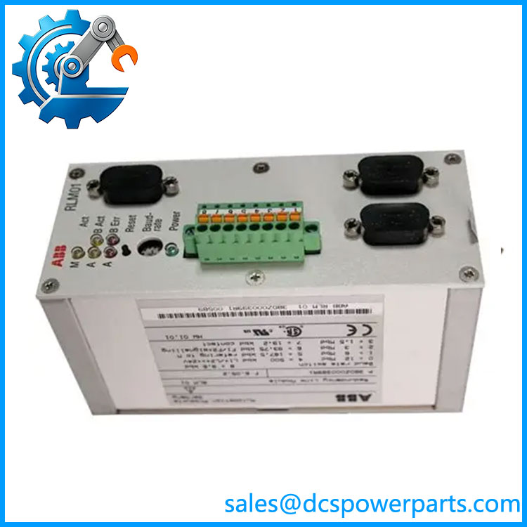
RLM02 3BSE091723R1
Three PROFIBUS interfaces
The A and B ports form the redundant side, while M provides the non-redundant connection. The arrangement is straightforward once the topology is understood, but it should not be confused with a conventional three-port Ethernet switch. The is specifically designed around PROFIBUS RS-485 communication and its redundancy mechanism.
Automatic line selection
The module monitors communication activity and error conditions on the three PROFIBUS lines and automatically selects the appropriate redundant path. ABB describes the unit as acting like an active switch while also regenerating the incoming signal.
For commissioning teams, this means that network diagnostics should include both physical cable paths rather than testing only whether the PROFIBUS master can communicate with the slave.
12 Mbit/s maximum transmission rate
The supports the standard PROFIBUS rate range from 9.6 kbit/s to 12 Mbit/s. The selected baud rate still has to be compatible with the complete PROFIBUS segment, including cable length, repeaters, connectors, and attached devices.
The 12 Mbit/s figure should therefore be treated as the module’s supported maximum, not as a guarantee that an arbitrary installed network can operate at 12 Mbit/s.
Communication monitoring and diagnostics
The module monitors communication activity and error status across its interfaces. ABB specifies front-panel indication and an alarm contact for fault signaling. The technical documentation identifies a normally closed alarm contact that opens in the event of an error, with a maximum switching current of 1 A and switching voltage below 60 VDC.
Functionally isolated RS-485 interfaces
The three serial interfaces are functionally isolated, with a specified 500 Veff test voltage. This is useful when assessing the electrical separation between the communication interface and connected PROFIBUS segments. It should not, however, be interpreted as universal galvanic isolation of every external installation component.
DIN-rail installation
The uses a 35 mm mounting rail and has a compact industrial enclosure with IP20 protection. Installation inside an appropriate cabinet or enclosure is therefore expected where environmental or touch-protection requirements demand more than the module itself provides.
Marine and industrial applications
ABB documentation identifies certification including CE, UL, CSA and DNV GL/type approval for marine use. The datasheet specifies marine environmental classes for temperature, humidity, vibration, EMC and enclosure.
For marine procurement, the exact installation arrangement and applicable certificate should still be checked against the project classification requirements rather than assuming every installation automatically meets every vessel or offshore requirement.
Related Products
- RLM01 — ABB PROFIBUS redundancy component from the same broader PROFIBUS infrastructure family. Verify the exact network architecture before treating it as a replacement for .
- PCO 011 — PROFIBUS DP connector with switchable bus termination, supporting connections up to 12 Mbit/s.
- PCO 012 — PROFIBUS DP connector with switchable termination and a programming/test connection.
- 3BDZ000397R1 — Power-supply filter associated with the documented marine certification arrangement for the .
- S900 Remote I/O — ABB remote-I/O ecosystem in which the can be used as part of the PROFIBUS network infrastructure.
- ABB Freelance PROFIBUS components — Network infrastructure components used alongside the for PROFIBUS DP installations.
- ABB System 800xA PROFIBUS network components — The is documented within ABB’s System 800xA PROFIBUS component catalog.
FAQ
Can I replace an with a standard PROFIBUS repeater?
Not automatically. A repeater regenerates and extends a PROFIBUS signal, while the specifically performs redundant A/B line management and conversion between redundant and non-redundant PROFIBUS lines. The network topology and redundancy requirement must be checked before substitution.
Can I hot-swap the ?
Do not assume unrestricted hot replacement. The is a powered communication device rather than a conventional plug-in I/O card. Any live replacement should follow the site’s approved PROFIBUS maintenance procedure and account for the resulting communication interruption or redundancy state.
Does the require a PROFIBUS slave address?
No. ABB specifically describes the as transparent for PROFIBUS configuration and states that it requires no slave address.
What PROFIBUS speed does the support?
The documented range is 9.6 kbit/s to 12 Mbit/s. The actual operating speed is determined by the network configuration and connected PROFIBUS devices.
Can one connect a single-interface field device to a redundant PROFIBUS network?
Yes. This is one of the primary applications documented by ABB. The single-interface device connects on the M side, while the A and B sides provide the redundant network path.
Does support PROFIBUS DP and FMS?
Yes. ABB identifies the for PROFIBUS DP/FMS applications.
What happens if one redundant PROFIBUS line fails?
The monitors the redundant lines and automatically selects the functioning communication path. ABB describes the module as monitoring the activity and error status of all three lines.
Is an I/O module?
No. It does not provide analog or digital process I/O. It is a PROFIBUS network communication and redundancy device positioned between PROFIBUS segments.
Does the 3BSE091723R1 part number identify the ?
Yes. ABB’s current product catalogs identify with article number 3BSE091723R1.
Does the operate from 24 VDC?
Yes. The ABB datasheet specifies 24 VDC operation, with typical current consumption of approximately 120 mA at 24 VDC.
Procurement Note
When sourcing an ABB 3BSE091723R1, match the complete article number rather than purchasing based only on the generic description “PROFIBUS redundancy module.” Confirm that the existing installation actually uses the A/B/M topology, check the three 9-pin Sub-D interfaces, verify the PROFIBUS transmission rate, and inspect the associated connectors and termination components.
For a replacement project, document the network before removing the existing device. Record which cable is connected to A, B, and M, the configured baud rate, termination locations, alarm wiring, and the connected master/slave topology. This is particularly important on older installations where network drawings may no longer match the physical cabinet.
The ABB 3BSE091723R1 is also a good example of why a visually similar PROFIBUS component should not be treated as an automatic substitute. The has a specific redundancy function, transparent PROFIBUS behavior, three RS-485 interfaces, and defined electrical isolation characteristics.
For surplus or refurbished inventory, verify the actual nameplate, article number, connector condition, DIN-rail housing, LED operation, and communication performance. If the application is marine, request confirmation of the applicable certification and associated installation requirements rather than relying solely on a seller’s generic statement that the module is “marine approved.”