Description
Product Overview
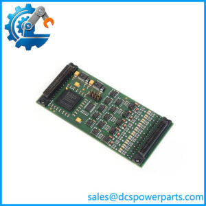
The SIGMATEK DDM163 05-008-163 is a digital conversion module in the DIAS industrial automation platform. It combines discrete signal acquisition and output switching in one module, allowing a machine controller to monitor field devices and operate compatible actuators. Eight digital inputs accept 24 V DC signals from devices such as proximity sensors, limit switches, and auxiliary machine contacts. Eight positive-switching digital outputs control suitable loads, including indicator lamps, relays, and solenoid valves. This mixed-I/O arrangement is useful in machine-control cabinets where input and output points must be handled within the same DIAS system.
On the output side, each channel supports a maximum continuous load current of 2 A, while the total current across all eight channels must remain at or below 6 A under continuous operation. Short-circuit protection is provided, and the documented switching delay is less than 200 microseconds for both turn-on and turn-off. Input thresholds are also defined: a low signal is below 8 V, a high signal is above 14 V, and the typical switching threshold is 11 V. Input delay is approximately 5 ms, which matters when processing fast pulses or short-duration sensor signals. The module draws its logic supply from the DIAS +5 V bus, typically 20 mA and up to 40 mA, separately from the field power requirements.
For maintenance and replacement work, the SIGMATEK DDM163 must be matched to the existing DIAS hardware and terminal arrangement. The manufacturer’s documentation identifies the DKL013 terminal module as the required connection component and specifies operating temperatures from 0°C to +60°C. Before installation, verify the terminal assignment, separate input and output supply circuits, output load current, and inductive-load suppression. A replacement that fits physically can still cause field faults if the wiring or load assumptions differ. For legacy equipment, preserve the original I/O mapping and application configuration, then test every channel before releasing the machine to production.
Product Introduction (Non-Templated)
A mixed-I/O module failure can affect both sensor monitoring and actuator control, even when the machine controller itself remains operational. The SIGMATEK DDM163 combines eight digital inputs and eight short-circuit-protected outputs, with each output rated for up to 2 A continuous current and an overall output limit of 6 A.
For a DIAS system repair or legacy I/O replacement, confirm the DKL013 terminal module, 24 V field wiring, and load-current distribution before installation. Pay particular attention to solenoid coils and other inductive loads.
Key Technical Specifications
| Parameter | Value |
|---|---|
| Product Model | DDM163 |
| Manufacturer | SIGMATEK |
| Part Number | 05-008-163 |
| Product Type | Digital conversion / mixed I/O module |
| Automation Series | DIAS |
| Digital Inputs | 8 channels |
| Digital Outputs | 8 channels |
| Output Switching Type | Positive switching |
| Field Supply Voltage | 18–30 V DC |
| Typical Input Voltage | +24 V DC |
| Maximum Input Voltage | +30 V DC |
| Input Signal Low | Below +8 V |
| Input Signal High | Above +14 V |
| Typical Input Switching Threshold | +11 V |
| Typical Input Current | 5 mA at +24 V |
| Typical Input Delay | 5 ms |
| Maximum Continuous Output Current | 2 A per channel |
| Maximum Aggregate Output Current | 6 A across all 8 channels |
| Output Short-Circuit Protection | Yes |
| Maximum Output Voltage Drop | 1 V |
| Maximum Off-State Residual Current | 12 µA |
| Output Turn-On Delay | Less than 200 µs |
| Output Turn-Off Delay | Less than 200 µs |
| Inductive Load Energy | Maximum 0.65 J per channel; 1.95 J per group of four |
| DIAS Bus Supply | +5 V DC |
| DIAS Bus Current Consumption | 20 mA typical; 40 mA maximum |
| Required Terminal Module | DKL013, part number 05-024-013 |
| Connection Type | 17-pole, three-row spring terminal strip |
| DIAS Bus Module Identification | 16#02 |
| Hardware Version Listed | 6.0 |
| Operating Temperature | 0°C to +60°C |
| Storage Temperature | −20°C to +85°C |
| Humidity | 0–95%, non-condensing |
| Dimensions | Approximately 93 × 80 × 98 mm |
| Condition | Depends on supplied inventory and inspection results |
Source: SIGMATEK DDM 163 technical documentation.
Important electrical limitation: The 2 A rating applies to an individual output channel, not to all eight outputs simultaneously. The combined continuous output load must not exceed 6 A. For inductive loads, follow the manufacturer’s suppression and grounding recommendations to reduce voltage spikes and unintended output behavior.
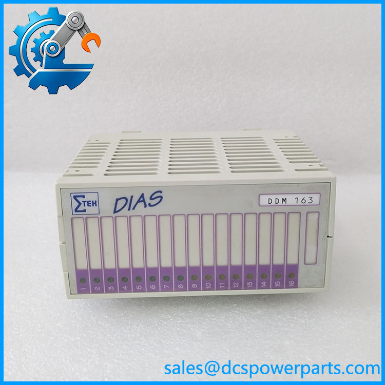
DDM163
Related Products
The following items are relevant to DDM163 maintenance and system compatibility. The distinction between a direct replacement, a connection accessory, and a system-level component matters when planning a repair.
1. SIGMATEK DKL013 — Required terminal module for the DDM163 according to the manufacturer’s documentation. It provides the field wiring interface for the eight inputs, eight outputs, supply connections, and ground. Verify the terminal block’s condition and part number when replacing the I/O module.
2. SIGMATEK DCP161 — DIAS processor module used for controller-level processing in compatible installations. The DCP161 and serve different roles: the DCP161 executes control logic, while the handles discrete field signals. Confirm the installed system configuration before pairing or substituting hardware.
3. SIGMATEK DCP181 — A processor-model comparison candidate for DIAS system assessment. It should not be treated as a direct replacement because it performs a different control-system function. Verify the applicable DIAS architecture and application compatibility before considering a controller change.
4. SIGMATEK DDI-series digital input modules — Input-only modules are relevant when a machine requires additional discrete input capacity without adding more output channels. They cannot replace the ‘s output-switching functions, so use them only when the existing control design supports a separate output module.
5. SIGMATEK DIAS digital output modules — Output-only modules can support applications requiring additional actuator-control points. Compare voltage, channel current, total current limits, output protection, terminal arrangements, and controller configuration before selecting a substitute.
6. SIGMATEK DIAS power-supply modules — These provide system power for the applicable DIAS installation. When troubleshooting a , verify both the +5 V DIAS bus supply and the separate 24 V field supply; a power fault can resemble a failed I/O module.
7. SIGMATEK DIAS rack or mounting assembly — The mechanical and electrical mounting arrangement must match the installed module and terminal system. Confirm the backplane interface, mounting hardware, and connector alignment before fitting a replacement.
8. SIGMATEK LASAL engineering environment — Relevant to supported SIGMATEK controller programming and configuration. Use the software and project version appropriate to the installed controller when checking I/O mapping, signal processing, and application behavior.
Selection note: DKL013 is the documented terminal-module requirement. The other related items are system-level or functional comparisons, not verified plug-in replacements for .
Frequently Asked Questions (FAQ)
1. Is the SIGMATEK an 8-channel input module or a mixed-I/O module?
It is a mixed-I/O module with eight digital inputs and eight digital outputs. The inputs read 24 V DC field signals, while the outputs switch compatible loads using positive switching. Replacing it with an input-only module would leave the eight output functions unserved.
2. Can I use all eight outputs at 2 A simultaneously?
No. Although each output supports up to 2 A continuous current, the manufacturer’s total-current limit is 6 A across all eight outputs.
For example, four channels drawing 1.5 A each would already total 6 A. Adding another energized load would exceed the specified aggregate limit. Calculate the maximum simultaneous load, including startup behavior, before connecting actuators.
3. Can I hot-swap the while the DIAS system is running?
Do not assume hot-swap capability. The available technical documentation identifies the required terminal module and electrical connections but does not establish that live insertion or removal is permitted.
Before replacing the module:
- Stop the machine using its approved procedure.
- Isolate the relevant power sources.
- Confirm that hazardous actuator movement and stored energy are controlled.
- Verify the correct installation procedure for the specific DIAS hardware.
Restore power only after checking terminal seating, wiring, and grounding.
4. Does the respond quickly enough for high-speed sensors?
That depends on the signal timing. The documented typical input delay is approximately 5 ms, which may be too slow for high-speed pulse counting or short-duration events. The output switching delay is less than 200 microseconds, but that does not make the input channels suitable for high-speed counting.
For rapid pulses, encoder signals, or time-critical measurement, use a module specifically rated for that function and confirm the application’s response-time requirements.
5. Which terminal module is compatible with the ?
The manufacturer’s documentation specifies DKL013, part number 05-024-013. Its three-row, 17-pole spring terminal arrangement provides the documented connection interface.
Before ordering, compare the installed terminal module’s part number and inspect its wiring condition. Do not assume that a visually similar terminal assembly has the same pin assignment.
6. How can I verify a new-surplus is authentic and functional?
A new-surplus description alone does not prove original packaging, operating condition, or successful testing.
Ask for:
- Photographs of the model label and part number 05-008-163.
- Evidence of the hardware version and connector condition.
- Available storage and provenance records.
- A test report identifying whether the unit was visually inspected, powered up, or tested with a compatible DIAS system.
For a functional test, check all eight inputs, all eight outputs, the status LEDs, and the output protection behavior under an approved test procedure. A visual inspection alone cannot establish full operating performance.
7. What should I check before replacing a in a legacy machine?
Use this commissioning checklist:
- Electrical supply: Verify 18–30 V DC field power and the +5 V DIAS bus supply.
- Terminal arrangement: Confirm compatibility and the documented input/output terminal assignments.
- Load distribution: Keep each output at or below 2 A and the total continuous output load at or below 6 A.
- Inductive loads: Check coil suppression, grounding, and wiring separation.
- Application configuration: Preserve the original I/O mapping and confirm that the controller recognizes the replacement.
- Functional test: Test every input and output channel before returning the machine to production.
For maintenance teams, the critical acceptance criterion is not simply that the replacement powers up. It must correctly read the connected field signals and switch the intended loads under the machine’s normal operating conditions.