Description
Key Technical Specifications
| Parameter | Specification |
|---|---|
| Manufacturer | Shinkawa Sensor Technology Co., Ltd. |
| Model | VM-742B1-1 |
| Product Series | VM-7 Monitoring System |
| Product Type | Network Communication Module |
| Installation Position | Slot C1, Upper Position |
| Communication Port A | Modbus/TCP |
| Communication Port B | Not Used / Blank |
| Ethernet Standard | 10Base-T / 100Base-TX |
| Network Connector | RJ-45, rack rear panel |
| Communication Protocol | Modbus/TCP |
| Ethernet Connections | 2 connections |
| Network Data | Measurement values, alarm status, gap voltage, diagnostic information |
| Analysis Software Communication | Not included in this model configuration |
| Module Power Consumption | 15 W maximum |
| Operating Temperature | 0°C to +65°C |
| Operating Temperature for Non-incendive Applications | 0°C to +60°C |
| Storage Temperature | -30°C to +85°C |
| Relative Humidity | 20–95% RH, non-condensing |
| Maximum Module Weight | 0.5 kg |
| Installation | Shinkawa VM-761B / VM-762B instrument rack |
Important identification detail: The VM-742B1-1 is the upper-slot C1 configuration. Its Port A supports Modbus/TCP, while Port B is unused. It is not the same communication configuration as VM-742B1-2 or VM-742B1-3.
Product Introduction
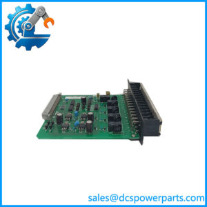
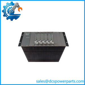
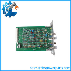
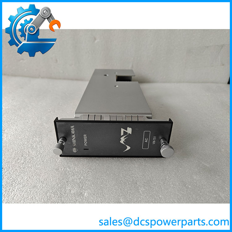
Shinkawa VM-742B1-1 Network Communication Module
The Shinkawa VM-742B1-1 is a network communication module for the VM-7 machinery monitoring system. Installed in rack position C1, it transfers vibration monitoring measurements, alarm conditions, gap voltage, and diagnostic information to supervisory equipment through Modbus/TCP over Ethernet.
Its main function is to connect machinery protection data with plant-level monitoring and control systems. The RJ-45 interface and two Ethernet connections support industrial network integration, making this module relevant to turbine, compressor, and rotating equipment monitoring installations.
VM-742B1-1
Application Scenarios & Field Pitfalls
Engineering Pain Point
A turbine monitoring system reports vibration alarms locally, but the plant DCS receives no updated measurement values. Maintenance personnel can see the problem on the monitoring rack while the control room operates with incomplete machinery information.
This is where the VM-742B1-1 becomes important. It provides the Modbus/TCP communication path between the VM-7 monitoring rack and the supervisory network. Replacing the communication module without checking the rack position, network configuration, and host-side register mapping can leave the original communication fault unresolved.
Typical Applications
- Power Generation: Transferring turbine bearing vibration and displacement measurements to the plant DCS.
- Oil & Gas: Communicating compressor vibration measurements and alarm conditions to centralized machinery monitoring systems.
- Petrochemical: Connecting rotating equipment protection racks with plant-level supervisory systems.
- Marine Engineering: Transmitting machinery condition information from monitoring racks to centralized engine-room monitoring systems.
Technical Pitfalls to Avoid
1. Incorrect Slot Position
The VM-742B1-1 is designed for slot C1, the upper communication position.
Do not confuse it with VM-742B2-1, which is intended for slot C2. The two models have corresponding Modbus/TCP functions but different physical installation positions.
Verify the rack configuration before ordering. A matching communication protocol does not guarantee mechanical interchangeability.
2. Ethernet Configuration and Network Addressing
The module supports Ethernet 10Base-T / 100Base-TX communication.
The documented default Modbus/TCP settings include:
- IP address: 192.168.8.1
- Subnet mask: 255.255.255.0
- Port number: 502
- Slave ID: 1
- Communication timeout: 10 seconds
These are documented defaults, not guaranteed settings for an operating installation. Check the existing network configuration before replacing the module. An incorrect IP address or subnet configuration can prevent communication even when the hardware is functioning normally.
3. Confusing Modbus/TCP with Analysis Software Communication
This is an important ordering distinction.
The VM-742B1-1 provides Modbus/TCP through Port A. Port B is blank. It does not provide the separate TCP/IP analysis software communication configuration found in VM-742B1-3.
If the existing system uses both fieldbus communication and machinery analysis software, select the correct VM-742B configuration rather than assuming all VM-742B modules have identical port assignments.
Field Engineering Recommendation: Before removing the existing module, record its IP address, subnet mask, network cable connection, and communication settings. After installation, verify actual measurement values and alarm status at the supervisory system rather than relying solely on the communication LEDs.
Related Products
The following components belong to the Shinkawa VM-7 machinery monitoring architecture. Their functions differ, and they should be selected according to rack position and communication requirements.
| Model | Product Description | Compatibility and Application |
|---|---|---|
| VM-742B2-1 | Network Communication Module, C2 | Lower-slot counterpart to VM-742B1-1. Provides Modbus/TCP communication through the C2 position. |
| VM-742B1-2 | Modbus/RTU Communication Module | Upper-slot configuration for RS-485 Modbus/RTU communication instead of Modbus/TCP. |
| VM-742B1-3 | Analysis Software Communication Module | Upper-slot configuration for TCP/IP communication with machinery analysis software. |
| VM-742B1-4 | Dual-Protocol Communication Module | Supports Modbus/RTU on Port A and Modbus/TCP on Port B. Useful when both interfaces are required. |
| VM-742B1-5 | Modbus/TCP and Analysis Communication Module | Combines Modbus/TCP on Port A with analysis software communication on Port B. |
| VM-741B | Local Communication and Phase Marker Module | Handles local communication and phase-marker functions within the VM-7 monitoring architecture. |
| VM-701B | Vibration/Displacement Monitor Module | Monitors shaft vibration and displacement signals from rotating machinery. |
| VM-702B | Absolute Vibration Monitor Module | Provides absolute vibration monitoring for machinery condition assessment. |
| VM-751B | Primary Power Supply Module | Supplies primary power to the VM-7 monitoring rack. |
| VM-761B | VM-7 Instrument Rack | Provides the rack infrastructure and rear-panel communication connections for compatible monitoring modules. |
Procurement and Replacement Checklist
Before purchasing the Shinkawa VM-742B1-1, verify:
- Exact model designation: VM-742B1-1.
- Existing installation position: C1, upper slot.
- Required communication protocol: Modbus/TCP.
- Port assignment: Port A active, Port B blank.
- Existing IP address and network settings.
- Compatibility with the installed VM-761B or VM-762B rack.
- Hardware revision and firmware compatibility.
- Condition and functional communication test results.
Final engineering note: If the application requires redundant communication paths, confirm whether both C1 and C2 communication modules are installed. A single VM-742B1-1 does not, by itself, establish a redundant network architecture.