Description
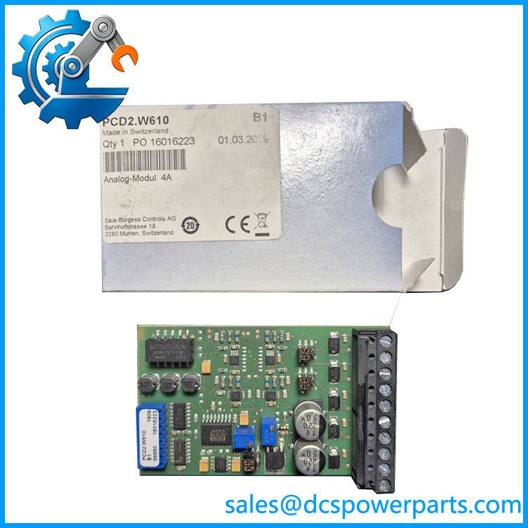
SAIA PCD2.W610 | 4-Channel 12-Bit Analog Output Module | Industrial PLC Control
Key Technical Specifications
| Parameter | Specification |
|---|---|
| Manufacturer | Saia-Burgess Controls |
| Model | PCD2.W610 |
| Product Type | Analog Output Module |
| Controller Family | Saia |
| Number of Outputs | 4 |
| Resolution | 12 bit |
| Voltage Range | -10…+10 V |
| Alternative Voltage Range | 0…10 V |
| Current Range | 0…20 mA |
| Range Selection | Jumper selectable |
| Galvanic Isolation | No |
| Output Protection | Short-circuit protected |
| D/A Conversion Time | Typically 10 µs |
| Voltage Load | >3 kΩ |
| Current Load | <500 Ω |
| Accuracy at 25°C | ±0.5% voltage; ±0.8% current |
| Temperature Error | ±0.1% voltage; ±0.2% current over 0…55°C |
| Internal Consumption | Max. 110 mA from +5 V bus |
| External Supply | Max. 100 mA when current outputs are used |
| Terminal | Pluggable 10-pole screw terminal block |
| Wiring Capacity | Up to 1.5 mm² |
The OEM manual specifies 4 short-circuit-protected channels, 12-bit digital representation from 0 to 4095, and a typical D/A conversion time of 10 µs. It also confirms that the uses jumper selection for bipolar voltage, unipolar voltage, and current output configurations.
Product Introduction
The SAIA . is a four-channel analog output module for the Saia PLC platform, intended for applications where the controller must generate continuous voltage or current reference signals rather than simple discrete ON/OFF commands. Each channel uses 12-bit resolution and can be configured for -10…+10 V, 0…10 V, or 0…20 mA operation, giving engineers flexibility when interfacing drives, valves, actuators, controllers, and instrumentation.
The SAIA . is particularly useful in existing installations where the control program, I/O addressing, and field wiring are already established. Its output channels are not galvanically isolated, so the field-side grounding arrangement must be reviewed before installation. The module also has a relatively fast D/A conversion time, making it suitable for general analog control and faster setpoint applications within the limits of the connected equipment.
PCD2.W610
Application Scenarios & Field Pitfalls — The Engineer’s Perspective
Engineering Pain Point
A common problem with legacy analog-control systems is assuming that two modules with the same connector layout can be exchanged without checking the signal configuration. With the , the critical issue is the jumper configuration: the same module can be configured for bipolar voltage, unipolar voltage, or current output. A replacement should therefore be matched to the existing field signal—not simply installed according to the software I/O address.
Typical Applications
- Motor and drive control: Provides analog speed or reference signals to compatible drive systems.
- Valve and actuator control: Generates voltage or current commands for proportional control devices.
- Process regulation: Interfaces controllers with temperature, pressure, flow, and level control loops.
- Machine automation: Provides analog setpoints to external regulators, servo-related equipment, and instrumentation.
Technical Pitfalls to Avoid
1. Verify the jumper configuration before installation.
The is configurable, and the factory/default jumper arrangement should not be assumed to match the existing machine. The OEM documentation specifically identifies separate jumper settings for the output modes.
2. Do not treat the outputs as galvanically isolated.
The technical documentation specifies no galvanic separation. Grounding and common-reference arrangements therefore matter, particularly when the module interfaces with drives or equipment powered from a different electrical system.
3. Current output requires the external supply arrangement.
For current-output operation, the documentation specifies external current consumption up to 100 mA. Confirm the available supply and wiring before commissioning all four channels in current mode.
4. Do not confuse with W600.
Both belong to the .W6x0 family, but is the 0…10 V version, while provides the configurable bipolar/unipolar voltage and current functionality.
Related Products
- SAIA .W600 — Four-channel 12-bit analog output module dedicated to 0…10 V operation; simpler than the configurable .
- SAIA .W410 — Four-channel 8-bit analog output module with jumper-selectable voltage/current ranges; lower resolution than .
- SAIA .W400 — Four-channel 8-bit 0…10 V analog output module.
- SAIA .W605 — Six-channel electrically isolated analog output module with 10-bit resolution; relevant where channel count and isolation requirements differ.
- SAIA .W525 — -family analog I/O option for installations requiring a different analog signal arrangement.
- SAIA .W500 — Related analog I/O hardware for applications requiring additional analog channels.
- SAIA .M5 series — CPU/controller hardware that provides the control platform for compatible I/O modules.
- SAIA expansion system — The appropriate rack/controller architecture should be verified before substituting or expanding I/O.
Procurement Note
For a replacement, confirm the exact module designation, jumper settings, output mode, terminal arrangement, and existing hardware revision. The most important distinction is that this is a 12-bit configurable analog output module, not a digital output card. If the original installation uses 4–20 mA, also verify the actual field configuration rather than assuming that every was commissioned in current-output mode.