Description
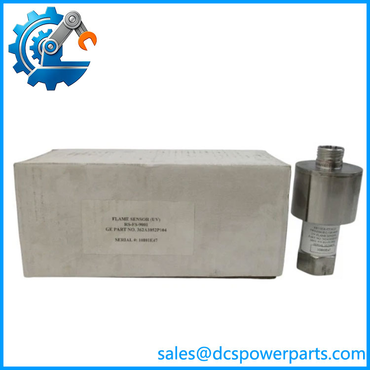
RS-FS-9001 362A1052P404 Flame Detector
Product Introduction
The RS-FS-9001 362A1052P404 is an industrial flame detector from the Reuter-Stokes Flame Tracker family, associated with GE combustion and gas-turbine applications. The exact part-number relationship is documented in a Reuter-Stokes parts matrix, which identifies RS-FS-9001 as the equivalent of GE 362A1052P404. The unit is designed to monitor flame radiation and provide a continuous signal representing flame intensity to the combustion control or burner management system. This makes it a field sensing device rather than a controller, PLC I/O module, or conventional DCS card.
The RS-FS-9001 362A1052P404 uses a silicon-carbide photodiode. SiC sensing is particularly useful where longer-wavelength ultraviolet flame radiation must be detected in combustion environments affected by fuel mist, steam, water injection, or low-NOx burner conditions. Available technical documentation describes the sensor as a two-wire, 4–20 mA flame sensor, with a minimum specified flame signal of approximately 5 mA and a nominal no-light output around 4 mA.
For gas-turbine maintenance, the RS-FS-9001 362A1052P404 should be considered part of the combustion safety chain. Its installation geometry, viewing angle, sapphire window condition, cooling arrangement, wiring polarity, and flame-threshold settings can all affect the resulting signal. The detector is also associated with multiple historical GE/Reuter-Stokes part-number equivalents, so replacement should be based on the complete part number and the installed application rather than on the RS-FS-9001 model name alone.
Technical Specifications
| Specification | Details |
|---|---|
| Product Model | RS-FS-9001 |
| GE Part Number | 362A1052P404 |
| Manufacturer / Brand | Reuter-Stokes / GE |
| Product Type | Flame Detector / Flame Scanner |
| Sensing Technology | Silicon Carbide (SiC) photodiode |
| Detection Principle | UV flame radiation |
| Output Signal | 4–20 mA |
| Supply Voltage | 12–30 VDC, nominal 24 VDC |
| Response | Fast flame-extinction response; published secondary data indicates <25 ms |
| Process Connection | 3/4-inch NPT internal thread |
| Electrical Connector | MIL-C-38999 Series III, size 15, 5-pin |
| Sensor Window | Sapphire |
| Housing | Sealed metal construction |
| Process Pressure | Up to approximately 400 psi according to secondary technical documentation |
| Ambient Temperature | Approximately -30 to +150 °C; cooling arrangements can extend allowable temperature |
| Flame Detection Signal | Continuous analog flame-intensity output |
| Installation | Direct flame-viewing installation with appropriate sighting/cooling hardware |
| Typical Application | Gas turbines, industrial burners, boilers and combustion safety systems |
The table combines information from the RS-FS-9001 operating documentation and secondary technical records. Some environmental and mechanical values vary between documentation revisions and installation configurations, so the original equipment documentation should take precedence for a safety-critical replacement.
RS-FS-9001 362A1052P404
Main Features and Engineering Considerations
SiC Flame-Sensing Technology
The RS-FS-9001 uses a silicon-carbide photodiode to detect the ultraviolet radiation associated with combustion. This technology is useful in applications where conventional flame sensing can be affected by water injection, steam, fuel atomization, or other combustion-system conditions. The manufacturer documentation specifically discusses SiC sensing for difficult flame-monitoring environments.
Continuous 4–20 mA Flame Signal
The sensor provides a continuous analog output rather than simply a binary flame-present contact. This allows the receiving controller to monitor flame intensity and establish appropriate flame-on and flame-off thresholds. Field-test documentation states that a no-light sensor should normally produce approximately 3.7–4.1 mA, while the specified minimum flame intensity produces at least 5 mA.
Fast Flame-Out Detection
Fast response is important in turbine and burner safety systems. A loss-of-flame condition must be recognized quickly enough for the associated fuel-control and trip logic to respond. Secondary technical documentation lists a response time below 25 ms for flame extinction. Treat this as an application-specific published value rather than assuming every installation will achieve identical system-level shutdown timing.
High-Temperature Installation
The sensor may be exposed to substantial radiant and conducted heat near a combustion chamber. Published information gives an operating range around -30 to +150 °C, with cooling arrangements available for higher-temperature installation conditions. The actual allowable temperature at the detector body depends on the cooling arrangement and installation geometry.
Established GE/Reuter-Stokes Part Number Relationship
A particularly useful procurement detail is the direct mapping between RS-FS-9001 and GE 362A1052P404. The Reuter-Stokes parts matrix also lists numerous older GE part numbers that RS-FS-9001 replaces, including 362A1052P001, P004, P104, P203, P243, P303 and P304. This makes the complete part number important when evaluating legacy turbine installations.
Application Scenarios
Gas Turbine Flame Monitoring
The RS-FS-9001 is primarily associated with industrial gas-turbine combustion systems. It monitors individual burner flame conditions and supplies the resulting flame signal to the turbine control or combustion safety architecture.
Burner Management Systems
The 4–20 mA signal can be evaluated by burner management or flame-monitoring equipment for flame-present, flame-out, and low-flame conditions.
Industrial Boilers
The detector can be used for combustion monitoring on burners where continuous flame confirmation is required before and during fuel operation.
Industrial Heating Equipment
Applications can include process heaters, furnaces and other combustion equipment where UV flame detection is appropriate.
Low-NOx Combustion
SiC-based sensing can be useful in combustion arrangements where steam or water injection and fuel-air conditions can make flame detection more difficult.
Engineer’s Guide: Field Pitfalls
1. Do not confuse the sensor with the flame-monitoring controller.
RS-FS-9001 is the field detector. The receiving flame-monitoring/control equipment performs the higher-level decision logic.
2. Check the actual 4–20 mA loop.
A current reading around 4 mA with no flame is expected according to the service documentation. Do not immediately interpret a low current as a failed sensor without checking supply voltage, loop wiring, connector condition and the optical path.
3. Clean the sapphire window.
Deposits on the viewing window can reduce the detected UV intensity and create an apparent low-flame condition. The maintenance documentation specifically calls for checking window cleanliness during field testing.
4. Verify sighting before changing thresholds.
A weak flame signal is not necessarily a sensitivity-setting problem. Incorrect detector alignment, burner geometry, dirty optics, excessive heat, or cooling problems can all produce misleading readings.
5. Confirm the cooling arrangement.
If the installation uses air or water cooling, verify that the cooling system is operating correctly before commissioning a replacement detector. A detector rated for a lower body temperature should not simply be installed in a hotter location.
6. Match the complete part number.
RS-FS-9001 has multiple historical GE/Reuter-Stokes equivalents. Do not substitute another 362A1052P-series detector solely because the prefix looks similar. The suffix can correspond to a different configuration or application.
7. Test the complete safety chain.
After replacement, verify detector output, flame-on threshold, flame-off threshold, receiving controller input, alarm logic, permissives and fuel-trip behavior. A sensor replacement is not complete until the associated combustion safety function has been tested.
Frequently Asked Questions
What is RS-FS-9001 362A1052P404?
It is a Reuter-Stokes / GE industrial flame detector, with RS-FS-9001 being the Reuter-Stokes model and 362A1052P404 the corresponding GE part number.
Is RS-FS-9001 a PLC module?
No. It is a field-mounted flame sensor used as part of a combustion monitoring and safety system.
What type of sensing element does it use?
The RS-FS-9001 uses a silicon-carbide photodiode for flame-radiation detection.
What signal does it provide?
The documented RS-FS-9001 configuration uses a two-wire 4–20 mA output representing flame intensity.
What is the normal signal with no flame?
The operating documentation gives approximately 3.7–4.1 mA as a practical no-light check range. The specified minimum flame intensity produces at least approximately 5 mA.
What is the difference between RS-FS-9001 and 362A1052P404?
For this configuration, they identify the same flame-detector assembly: the Reuter-Stokes model is RS-FS-9001 and the corresponding GE part number is 362A1052P404.
Can another 362A1052P-series unit be substituted?
Not automatically. The parts matrix shows multiple 362A1052P-series numbers associated with different historical configurations. Verify the complete part number, detector installation, electrical interface, flame characteristics and receiving controller before substitution.
Procurement Note
For RS-FS-9001 362A1052P404, the critical purchasing information is the complete detector part number, connector configuration, mechanical connection, cooling arrangement, and compatibility with the existing flame-monitoring circuit.
For an operating gas turbine or burner management system, do not qualify a replacement only by physical fit. Before installation, compare the original detector’s part number and wiring, confirm the 4–20 mA loop requirements, inspect the sapphire window and optical alignment, verify cooling, and document the existing flame-on/flame-off thresholds. After installation, perform a controlled flame-signal and safety-chain test before returning the combustion system to normal operation.