Description
MVME5100 VMEbus Single-Board Computer
Product Overview
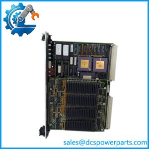
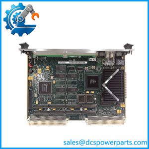
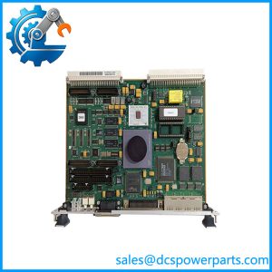
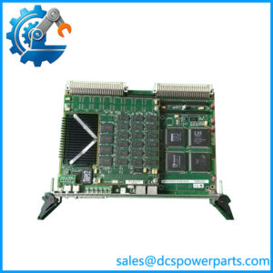
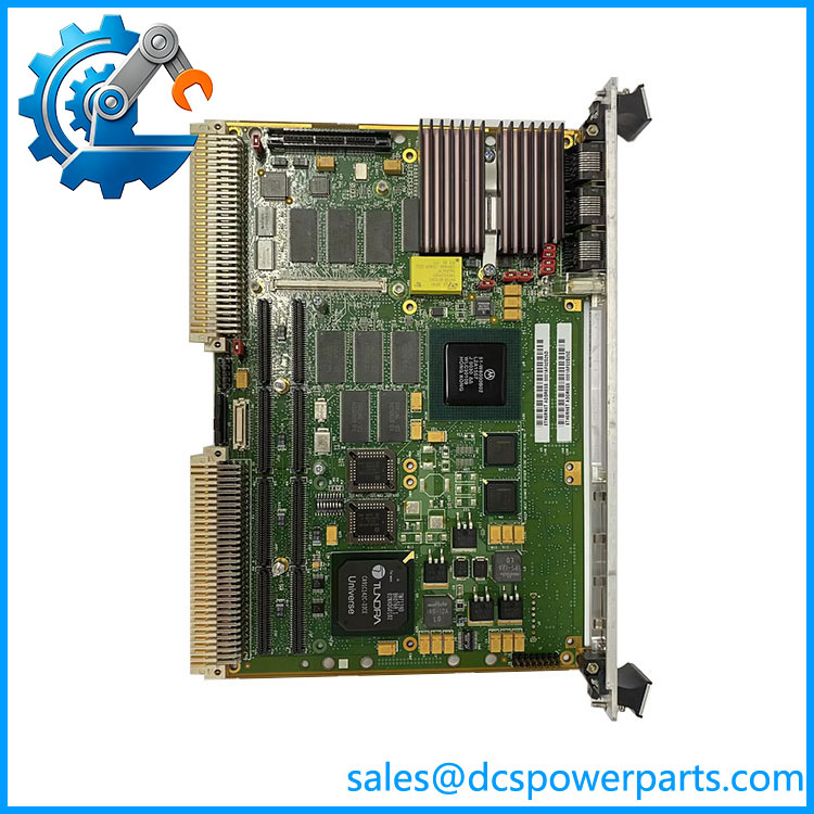
MVME5100 is a 6U VMEbus single-board computer developed by Motorola Computer Group and later carried through the Emerson Network Power and Abaco Systems lineage. It sits at the top of the PowerPlus II VME architecture as a slot-1 system controller: a single 6U board that carries the CPU, main memory, boot firmware, dual Ethernet ports, serial console and PCI mezzanine expansion, while still handing the integrator a P2 rear-I/O path to the field wiring. Its role in a rack is not to be a fast desktop but to be the deterministic master that boots in seconds, moves VME slave data in A32/D64 block transfers, and keeps running for a decade inside a cabinet nobody wants to open.
The processor is an MPC750 at 450 MHz or an MPC7400 at 400 MHz with AltiVec, backed by 1 MB or 2 MB of backside L2 cache, a 100 MHz front-side bus and PC100 ECC SDRAM that starts at 64 MB, reaches 512 MB on board, and extends to 1.5 GB with RAM500 mezzanines. The Hawk bridge and memory controller delivers 582 MB/s sustained read and 640 MB/s burst write while leaving 264 MB/s of usable PCI bandwidth — the figure that actually decides whether a PMC card can stream digitised field I/O into memory without stalling the control task.
The problem MVME5100 was engineered to close is I/O continuity. Motorola historically sold two VME tracks: boards with rich on-board I/O behind a P2 transition module, and boards with spare PMC sites and almost no front-panel I/O. MVME5100 merges both into one part number. Jumper-selectable PMC mode is drop-in compatible with MVME2300 and MVME2400 rear I/O, while IPMC mode accepts an IPMC761 or IPMC712 to reproduce MVME2600/MVME2700 behaviour on already-installed MVME761 or MVME712M transition hardware. The board still occupies one VME slot with both PMC sites and both memory mezzanines fitted, which is what makes a like-for-like CPU refresh possible without touching the backplane.
Technical Specifications
| Parameter | Value |
|---|---|
| Product model | MVME5100 |
| Manufacturer | Motorola Computer Group (original design); Emerson Network Power / Abaco Systems |
| Product type | 6U VMEbus single-board computer (VME processor module, system controller) |
| Processor | MPC750 @ 450 MHz or MPC7400 @ 400 MHz with AltiVec; 32 KB/32 KB L1; 1 MB or 2 MB backside L2 |
| Front-side bus and memory | 100 MHz FSB; PC100 ECC SDRAM, 64/128/512 MB on board, up to 1.5 GB with RAM500 mezzanines |
| Memory and PCI bandwidth | 582 MB/s sustained read, 640 MB/s burst write; 264 MB/s PCI throughput |
| Flash and NVRAM | 17 MB flash (1 MB in two socketed PLCC boot devices plus 16 MB surface mount); 32 KB battery-backed NVRAM with time-of-day clock |
| VMEbus interface | VME64 (ANSI/VITA 1-1994, IEEE 1014), Tundra Universe controller; master A16–A32/D08–D64 with BLT, slave A24–A32; round-robin/priority arbiter, jumperable or auto-detect system controller, two LMA32 location monitors |
| Expansion | 2 × IEEE 1386.1 PMC slots, 32/64-bit, 33 MHz, 5 V signalling, 7.5 W per slot; 114-pin PCI expansion connector for PMCSPAN, adding up to four further PMCs |
| Network and serial | 2 × Intel 82559ER 10/100BaseTX (RJ-45); 2 × 16C550C asynchronous ports, EIA-574 DTE, 38.4 kbps EIA-232 / 115 kbps raw |
| Power | +5 V @ 3.0 A typ. (3.2 A typ. with MVME761 fitted), +12 V 8 mA, −12 V 2 mA |
| Mechanical and environment | 6U single slot, 233.4 × 160.0 mm, front panel 261.8 mm, 19.8 mm width; 0 to +55 °C commercial or −20 to +71 °C extended, 5–90% RH non-condensing, 2 G RMS random 20–2000 Hz, 400 LFM forced air recommended |
Key Features and Benefits
Two I/O personalities in one slot
Two IEEE 1386.1 sites accept a double-wide or two single-wide PMCs, and in PMC mode 64 pins from site 1 and 46 pins from site 2 route to P2 — so a 1553B, CAN, MVB or fieldbus mezzanine lands on the backplane terminals instead of trailing a cable out of the front panel. A 114-pin PCI expansion connector and PMCSPAN-002 stack two more slots on top, giving four additional PMCs while the board still holds a single VME position.
ECC memory and cache sized for scan-cycle determinism
Every DRAM byte is ECC-protected, so a stray bit is corrected and logged rather than crashing a controller at three in the morning. Repeated single-bit errors become a maintenance signal, not a plant trip. With 1–2 MB of backside L2 cache and a 100 MHz bus, a 5 ms control task still closes its window while Ethernet DMA and PMC transfers contend for the Hawk bridge.
Firmware that diagnoses before the OS loads
The PPCBug monitor runs power-up self test, memory and VMEbus diagnostics and an interactive debugger from a serial console before any operating system exists. A technician isolates a faulty board, a faulty slot or a faulty backplane with a terminal, not with a card swap. Four 32-bit timers and a watchdog that forces a hard reset keep a hung application from holding the VMEbus hostage.
Backplane-level backward compatibility
IPMC mode with IPMC761 reproduces the MVME761 rear-I/O layout; with IPMC712 it reproduces MVME712M, down to the D-50 narrow SCSI and three-port serial pinout. Existing marshalling, terminal blocks and P2 adapters stay untouched, so a CPU replacement is a mechanical task rather than a re-engineering project.
Sustained operation in a closed cabinet
Extended-temperature versions run from −20 to +71 °C against 0 to +55 °C for commercial stock, with 2 G RMS random vibration tolerance, 32 KB of battery-backed NVRAM retaining setpoints and calibration through a power cut, and a demonstrated MTBF of 190,509 hours. Boards are UL 94V-0 rated and qualified to FCC Part 15 Class A and EN55022 Class B.
Application Areas
Power generation: In combined-cycle and hydro plants, MVME5100 serves as the VME master of a legacy DCS or a turbine supervisory front end, polling vibration, bearing temperature and speed channels through a PMC or transition module while publishing to the plant LAN on its second Ethernet port. Its deterministic boot matters during a black start, when the control rack is repowered and must be scanning before the auxiliary systems come online.
Oil and gas: At compressor stations and metering skids, the board acts as the station controller in pipeline SCADA architectures — gathering flow, pressure and analyser data on serial and fieldbus mezzanines, running the local logic, and buffering to NVRAM so a custody-transfer totaliser survives an outage.
Metals, pulp and paper, cement: These plants carry VME racks from the 1990s that still run drive coordination and kiln or digester control. is the board that keeps that rack alive when the original CPU is no longer procurable, because the existing MVME761 transition module and its field terminations stay in place.
Rail and transport: With MVB or CAN on a PMC site, the board handles vehicle and wayside control duties, and the extended-temperature version covers enclosures that see summer heat without active cooling beyond cabinet airflow.
Semiconductor and medical equipment: As a tool controller in process equipment and an acquisition front end in imaging systems, pairs a 5 V PMC ecosystem with enough PCI bandwidth to move digitised samples without dropping frames.
Related Products
MVME5101 — same series, AltiVec-equipped MPC7400 variant at 400 MHz with up to 2 MB L2 cache, for signal-processing-heavy loads. MVME5110 — same PowerPlus II family with MPC7410 at 400 or 500 MHz, same I/O map, a frequency step above the base board. MVME5500 — direct upgrade path to a 1 GHz PowerPC 7457 with higher memory and PCI bandwidth, pin-compatible in most VME64 racks. MVME6100 — next-generation VME64x successor with a dual-core PowerPC, for new builds rather than like-for-like replacement. MVME2700 — previous-generation single-board computer whose MVME761 transition hardware and P2 adapters is designed to reuse. MVME761 — companion transition module providing DB-9 serial, HD-26 sync/async, parallel and RJ-45 Ethernet access at the rear. MVME712M — legacy transition module for three serial ports, narrow SCSI and parallel I/O, supported through IPMC712. IPMC761 — rear-I/O PMC card installed in site 1 to enable SBC/IPMC mode and legacy compatibility. PMCSPAN-002 — primary PCI expansion mezzanine, adding two PMC slots and accepting a secondary expansion for two more. RAM500-006 — 256 MB ECC SDRAM mezzanine, stacking with the on-board array to reach the 1.5 GB ceiling.
Installation and Maintenance
Pre-installation: Before the board goes into the rack, verify the slot-1 backplane position, confirm the +5 V rail can carry 3.0 A plus the PMC and mezzanine load (7.5 W per PMC site), and check that at least 400 LFM of forced air reaches the card cage — the 6U form factor is dense and the MPC750 dissipates continuously. Set the PMC/IPMC mode jumpers and the system-controller selection before power-up; a mis-set controller jumper on a multi-master bus will show up as arbitration faults rather than a clean boot failure. Seat fully on both P1 and P2, then fit the PMCSPAN-002 or RAM500 mezzanine only after the base board is confirmed to boot from the console.
Maintenance: Keep the PPCBug diagnostics output from the last known-good boot as a baseline, so a future memory or VMEbus test failure can be compared rather than judged in isolation. Log ECC single-bit corrections from the OS side — a rising count points to a failing DIMM, a hot spot or excessive supply ripple long before it becomes a double-bit fault. Replace the NVRAM backup battery on a scheduled cycle; a depleted cell silently drops setpoints and calibration on the next outage. When swapping a board, record the flash layout and boot image version first, since holds 17 MB of flash split between socketed boot devices and surface-mount application space, and reflashing the wrong region is the most common avoidable downtime.
Product Warranty
Every module is supplied tested against its original functional specification, with boot, memory, VMEbus and I/O paths verified on a bench fixture before dispatch rather than shipped on a visual inspection alone. Standard coverage is 12 months on the board and its socketed boot devices, with extended terms available for installed-base support contracts. Because these units keep critical racks running past their original design life, stock is held as graded, serial-tracked inventory with revision and firmware level recorded per unit, so a replacement matches the board it replaces instead of merely sharing a part number. orders ship with the configuration sheet, jumper settings for PMC or IPMC mode, and firmware version documented; technical support covers backplane compatibility, transition-module pairing and OS bring-up questions. Where a plant cannot tolerate a trial-and-error swap, advance-exchange and bench-tested spares are available so the rack is down for minutes, not for a procurement cycle.