Description
DEIF LSU-112DG Generator Load Sharing Unit
Key Technical Specifications
| Parameter | Specification |
|---|---|
| Model | LSU-112DG |
| Manufacturer | DEIF A/S |
| Product Family | Uni-line |
| ANSI Code | 90 |
| Main Function | Load sharing and generator power/frequency control |
| Application | Diesel and gas generator sets |
| Operating Modes | Stand-alone, grid parallel, multi-generator parallel |
| Measurement | Built-in power and frequency transducers |
| Speed Control | Two relay outputs |
| Governor Interface | Mechanical governor; electronic governor via EPN-110DN or EPQ-96/EPQ96-2 |
| Control Characteristic | Built-in P controller |
| Constant Power Mode | Supported |
| Isochronous Mode | Supported |
| Load Sharing | Generator-to-generator active load sharing |
| Unload Function | Dedicated unload input |
| Mounting | 35 mm DIN rail or base mounting |
| Self-Monitoring | Built-in microcontroller supervision |
| Status Indication | LED indication for power/status and control activity |
The LSU-112DG is designed to measure generator voltage and current, derive frequency and active power, and use those measurements for prime-mover control. DEIF specifies operation in stand-alone mode for frequency control, grid-parallel operation for power control, and parallel operation between generators for frequency and power control.
Control Settings
The controller uses adjustable parameters for the speed-control response. Documented settings include:
- TN: Minimum relay ON time, 25–500 ms
- XP: Proportional band, configurable around the rated power/frequency
- Frequency: 45–65 Hz
- Derating: 50–0% of rated power
- TP: Period time related to TN
- Power deadband: Normally ±2% of rated power
- Frequency deadband: Normally ±0.1 Hz
Actual ranges and jumper-dependent alternatives should be checked against the specific LSU-112DG revision and customization.
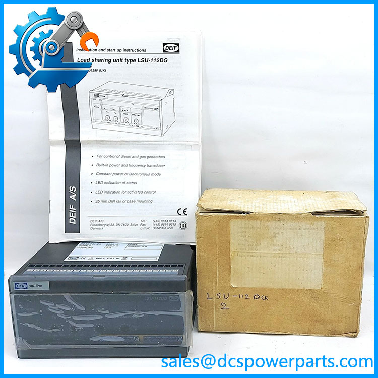
LSU-112DG
Product Introduction
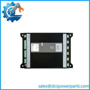
The DEIF LSU-112DG is a Uni-line load-sharing unit intended for diesel and gas generator applications. It measures generator voltage and current internally and derives the electrical quantities required for frequency and active-power control. Speed correction is issued through two relay outputs, allowing the unit to command increase or decrease of prime-mover speed.
In a multi-generator installation, one LSU-112DG is normally associated with each generator. The units exchange the required load-sharing information so generator output can be distributed according to the calibrated rating of each power unit. The calibration therefore matters: a replacement unit should not simply be installed with factory/default settings when the original system was customized for a particular generator.
Application Scenarios & Field Pitfalls
The is primarily a generator governor/load-sharing controller, not a general PLC or conventional protection relay. The important engineering work is getting the electrical measurement scaling and governor interface correct before attempting load sharing.
Typical applications:
- Diesel generator load-sharing systems
- Gas-engine generator plants
- Multiple-generator parallel operation
- Generator-to-grid active-power control
- Stand-alone generator frequency regulation
- Retrofit and maintenance of legacy DEIF Uni-line control panels
Engineer’s checks before replacement:
- Verify CT and voltage measurement configuration. The is customized according to the generator’s measuring voltage, measuring current, scaling, coupling arrangement, and calibration. The label contains configuration information that should be recorded before replacement.
- Check the governor interface. The unit is intended for mechanical speed governors, while electronic governors require an appropriate DEIF electronic potentiometer interface such as the EPN-110DN or EPQ-96/EPQ96-2. Do not assume the relay outputs can be wired directly to every electronic governor.
- Preserve the load-sharing calibration. Derating, proportional band, deadband, pulse timing, and power scaling directly affect how generators divide load. A replacement with incorrect settings can produce unequal loading or unstable governor behavior.
- Check the unload circuit and self-monitoring status. The unload input can command the generator toward zero power and disconnect its power output from the paralleling line. The green POWER indication also provides information from the internal self-monitoring function.
Related Products
- DEIF LSU-113DG — Based on the load-sharing function but adds outputs associated with low-power detection and reverse-power protection.
- DEIF LSU-114DG — Adds automatic start/stop functions to the control concept.
- DEIF LSU-122DG — Designed for reactive-power/VAr sharing rather than the ‘s active-power load-sharing role.
- DEIF EPN-110DN — Electronic potentiometer used to interface compatible DEIF control units with electronic speed governors.
- DEIF EPQ96-2 — Electronic potentiometer interface for governor control applications.
- DEIF FAS-113DG — Synchronizer with voltage control; handles synchronization rather than generator load sharing.
- DEIF FAS-115DG — Synchronizer with voltage matching.
- DEIF HAS-111DG — Paralleling relay for generator control systems.
- DEIF RMP-112D — Generator overload/reverse-power protection relay; protection function differs from the control role.
The DEIF Uni-line documentation specifically separates the , LSU-113DG, LSU-114DG and LSU-122DG by their load-sharing, protection, start/stop, and reactive-power functions.
Procurement Note
For a replacement , specify the complete type designation and DEIF order/acknowledgment number, not just “.” Record the measuring voltage, CT input configuration, rated generator power, scaling, supply voltage, coupling arrangement, governor interface, and any special calibration from the existing unit.
This is particularly important for legacy generator panels. Two units can have the same basic model designation while being customized differently for their respective generator installations. The DEIF installation documentation explicitly identifies these customized parameters on the unit label.