Description
GE IS200BICLH1BAA IGBT Drive/Source Bridge Interface Board
Product Introduction
The General Electric IS200BICLH1BAA is an IGBT Drive/Source Bridge Interface Board identified by the functional abbreviation BICL. It was manufactured for GE’s Mark VI control hardware and provides an interface between the main control electronics and associated bridge-interface circuitry such as BPIA, BPIB, or SCNV. This makes the GE IS200BICLH1BAA a specialized drive and power-conversion interface board rather than a conventional PLC digital I/O module. Its position in the control architecture is important because it handles bridge-related interface and monitoring functions while the primary control logic remains associated with the main control board.
The GE IS200BICLH1BAA uses two VME-style backplane connectors, identified as P1 and P2. Available technical records report bridge and ambient-temperature monitoring, a panel/system fault-string interface, and a PWM interface associated with fan-speed control. The board also contains a 1024-bit serial memory device and four relays. Unlike many GE Mark VI boards, the available descriptions report no onboard test points, fuses, adjustable hardware, or dedicated LED indicators. The control logic associated with the board is configured through the CPU of the main control board using an electronically programmable logic device.
From a procurement standpoint, the GE IS200BICLH1BAA should be matched by complete part number and hardware revision. The BICL family contains several related variants, including IS200BICLH1A, IS200BICLH1B, and other suffix configurations, and these should not be assumed interchangeable merely because the functional abbreviation is the same. The board is also static-sensitive and must be handled using appropriate ESD controls. For a replacement, compare the board label, VME connector arrangement, revision markings, rack position, associated bridge boards, and the existing system documentation before installation.
Technical Specifications
| Parameter | Specification |
|---|---|
| Product Model | IS200BICLH1BAA |
| Manufacturer | General Electric |
| Series | Mark VI / Speedtronic |
| Functional Abbreviation | BICL |
| Product Type | IGBT Drive/Source Bridge Interface Board |
| Primary Function | Drive/source bridge interface |
| Associated Interface Boards | BPIA, BPIB, SCNV |
| Rack Interface | VME |
| Backplane Connectors | P1, P2 |
| Temperature Monitoring | Bridge and ambient temperature |
| Fan Interface | PWM fan-speed control interface |
| Fault Interface | Panel and system fault-string interface |
| Serial Memory | 1024-bit serial memory device |
| Relays | 4 |
| Test Points | None reported |
| Fuses | None reported |
| Adjustable Hardware | None reported |
| Dedicated LEDs | None reported |
| Reported Rack Position | Slot 5 for BICLH1 configuration |
| Installation | VME-type control rack |
| Power Supply | Supplied through the applicable rack/backplane architecture; do not assign a standalone field voltage without the system drawing |
| Communication Protocol | No standalone Ethernet/fieldbus interface reported |
| Operating Temperature | Verify from the applicable Mark VI cabinet/system documentation |
| Protection Rating | Board-level IP rating not established; cabinet enclosure determines environmental protection |
The available sources do not establish a reliable standalone working-voltage, operating-temperature, or IP specification for the bare board. Those values should therefore be taken from the applicable Mark VI cabinet documentation rather than copied from generic PLC specifications.
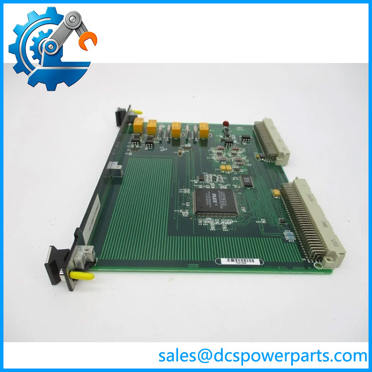
IS200BICLH1BAA
Main Features and Engineering Considerations
Bridge Interface Rather Than General-Purpose I/O
The most important identification point is the BICL function. The interfaces the main control board with bridge-related hardware, including BPIA/BPIB or SCNV configurations. Calling it a generic binary I/O module can lead to incorrect assumptions about field wiring, signal levels, and diagnostics. The board belongs to a drive/power-conversion control architecture.
VME Backplane Architecture
The board uses two backplane connectors, P1 and P2, for installation in the applicable VME rack. There are no additional external connectors reported on the board. This means that field devices should not be expected to connect directly to the BICLH1BAA in the manner of a conventional terminal I/O card. External signal routing is handled through the associated bridge and control hardware.
Temperature Monitoring
Bridge and ambient-temperature monitoring are part of the BICL function. These measurements provide the control architecture with information associated with the drive bridge and surrounding hardware. When troubleshooting a bridge-temperature alarm, technicians should verify the sensor circuit and associated bridge hardware rather than automatically replacing the BICL board.
Fan-Speed Control
The board includes a PWM interface associated with fan-speed control. The available technical description identifies the PWM output as an open-collector transistor arrangement. Fan operation therefore depends on the complete control path, including the main control board, BICL circuitry, fan hardware, and associated power/control wiring.
Relay and Fault Functions
Four relays are installed on the board, with relay diagrams printed on their surfaces. The board also participates in the panel and system fault-string interface. Because there are no reported onboard test points or adjustable hardware, troubleshooting generally requires examination of the surrounding system signals and rack-level interfaces rather than relying on local adjustment.
Revision and Compatibility Control
The full identifier should be retained in procurement records. Secondary documentation identifies multiple BICL revisions and related part numbers. One technical source reports three revisions for the exact listing and distinguishes functional revisions from an artwork revision. This is precisely why the physical board label and revision should be compared with the installed unit before substitution.
Application Scenarios
- GE Mark VI turbine control systems
- GE Speedtronic turbine-control cabinets
- IGBT drive systems
- Drive/source bridge interface applications
- Bridge temperature monitoring
- Ambient temperature monitoring
- Drive cooling-fan PWM control
- Panel and system fault-string interfacing
- VME-based GE control racks
Engineer’s Guide: Field Pitfalls
Do not treat the BICLH1BAA as a field I/O card.
Its documented role is bridge interfacing and monitoring. There is no evidence supporting a generic PLC-style 24 VDC digital-input/output specification.
Verify the associated bridge hardware.
The board interfaces with BPIA/BPIB or SCNV-related circuitry. A fault in those boards or the associated bridge can present symptoms that appear to originate from the BICL.
Check the VME seating.
The board uses P1 and P2 backplane connectors. Poor seating, contamination, oxidation, or mechanical misalignment can affect multiple functions simultaneously.
Check temperature circuits separately.
A bridge-temperature alarm does not automatically prove the BICLH1BAA has failed. Sensor wiring, bridge conditions, and associated interface circuitry should be checked first.
Check fan control before replacing the board.
The BICL participates in fan-speed PWM control. A failed fan, wiring issue, power problem, or upstream control signal can produce a cooling-related fault without a failed BICL board.
Do not expect onboard diagnostic indicators.
Available descriptions report no dedicated LEDs, test points, fuses, or adjustable hardware. Troubleshooting therefore relies heavily on system diagnostics and external measurements.
Use ESD precautions.
The board contains electronic memory and logic circuitry and should be handled as static-sensitive hardware.
Confirm the exact revision.
should not automatically be replaced with another BICL variant merely because its functional description looks similar.
Frequently Asked Questions
What is ?
is a GE BICL IGBT Drive/Source Bridge Interface Board used in Mark VI-related drive and turbine-control hardware.
What does BICL do?
BICL provides the interface between the main control board and bridge-related interface hardware. It also supports bridge/ambient temperature monitoring, fan-speed PWM control, and panel/system fault-string functions.
Is a PLC I/O module?
No. It should be treated as specialized bridge-interface hardware rather than a generic PLC I/O module.
What connectors are on the board?
The documented board has two backplane connectors, P1 and P2, which connect to a VME-type rack. No other board-mounted external connectors are reported in the available technical descriptions.
Does it have Ethernet?
No standalone Ethernet interface is documented for the board. Its primary connection is through the VME backplane and associated bridge/control hardware.
Does have onboard fuses or test points?
Available part-specific descriptions report no test points, fuses, or adjustable hardware.
How many relays are on the board?
The available technical description identifies four relays.
Where is the board installed?
The BICLH1 configuration is documented as a VME-rack board, with secondary technical records identifying slot 5 for the BICLH1 arrangement. The actual installed slot should always be confirmed against the cabinet drawing rather than assumed from a reseller listing.
What should be checked before purchasing a replacement?
Verify the complete part number, board revision, VME connector condition, rack position, associated BPIA/BPIB or SCNV hardware, temperature-sensing circuits, fan-control interface, and system fault wiring.
Procurement Note
For a legacy GE installation, the should be sourced as an exact BICL bridge-interface assembly rather than as a generic Mark VI I/O replacement. The practical compatibility checks are the complete part number, revision, VME rack configuration, associated bridge-interface boards, and the actual cabinet wiring.
For repaired or previously installed hardware, request photographs of the board label and both connector areas. Functional testing should cover backplane integrity, temperature-monitoring circuits, relay operation, fan PWM behavior, and system fault-string interaction where applicable. Do not assign a standalone field supply voltage or Ethernet specification unless it is confirmed from the actual Mark VI system documentation.