Description
ICS Triplex T8100 | Trusted TMR Controller Chassis | Safety System Replacement
Key Technical Specifications
| Parameter | Specification |
|---|---|
| Product Model | T8100 |
| Manufacturer | ICS Triplex / Rockwell Automation |
| Product Type | Trusted TMR Controller Chassis |
| System Family | Trusted T8000 |
| Architecture | Triple Modular Redundancy (TMR) |
| Backplane | Trusted Inter-Module Bus (IMB) |
| Processor Positions | 2 × triple-wide |
| I/O / Interface Positions | Up to 8 × single-wide |
| Typical System Supply | 24 VDC nominal |
| Backplane Supply Range | 20–32 VDC |
| Mounting | Swing frame / fixed frame / rear panel with T8380 |
| Cooling | Cabinet/system cooling arrangement |
| Compatible Processor Family | T8110 / T8111 series |
| Typical Applications | ESD, F&G, turbine control, critical interlocks |
| Programming Environment | Trusted Toolset / IEC 61131-3 |
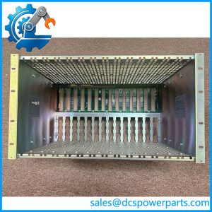
The T8100 is a chassis rather than a CPU module. Rockwell’s Trusted documentation describes the controller assembly as a T8100 chassis containing a Trusted TMR processor, communication interface, and associated interface hardware.
Available technical documentation identifies the T8100 backplane as the Trusted Inter-Module Bus (IMB) and provides positions for two TMR processor modules plus eight single-width I/O/interface modules.
Product Introduction
The ICS Triplex T8100 is the main controller chassis in a Trusted TMR safety system. It provides the mechanical mounting structure and internal IMB backplane that interconnect the Trusted processor, I/O, communication, and interface modules. The chassis itself does not execute the application logic; that function belongs to the installed Trusted processor module.
For maintenance teams, this distinction matters. A replacement should be evaluated against the complete Trusted configuration, including processor type, I/O population, communication modules, power architecture, firmware release, and system configuration. A mechanically compatible chassis does not automatically make an installed safety-system configuration interchangeable.
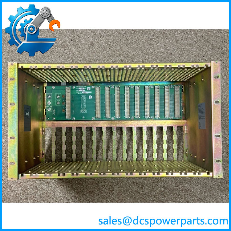
T8100
Application Scenarios & Field Pitfalls — Engineer’s Perspective
Engineering Pain Point
failures are not limited to obvious physical damage. Connector wear, backplane problems, incorrect module seating, grounding issues, or an incompatible chassis revision can create faults that appear to originate from the processor or I/O modules.
Typical Applications
- Emergency Shutdown (ESD) systems requiring redundant safety processing.
- Fire and Gas (F&G) systems where continuous diagnostic coverage and fault tolerance are required.
- Turbine and boiler protection systems using Trusted safety controllers.
- Critical process interlocks in applications where loss of a single hardware element must not immediately disable the safety function.
ICS Triplex documentation specifically lists fire and gas control, emergency shutdown, monitoring/control, and turbine control among Trusted TMR applications.
Technical Pitfalls to Avoid
- Do not confuse with T8110/T8111.
is the processor chassis. T8110/T8111 are processor modules installed in the chassis. Rockwell’s migration documentation explicitly separates the processor chassis from the T8110B processor module. - Verify the complete module population.
The chassis supports specific processor and I/O/interface arrangements. Check every installed module before replacement, especially TMR processor positions, communication interfaces, expander interfaces, and power arrangements. - Check the IMB and connectors carefully.
A replacement chassis with damaged or contaminated backplane connectors can produce intermittent module faults that are difficult to distinguish from processor or I/O failures. - Do not treat the chassis as a standalone safety controller.
The safety function depends on the complete Trusted architecture. Processor firmware, application configuration, I/O modules, communication interfaces, power supplies, and system configuration all remain relevant after a chassis replacement. - Control cabinet requirements matter.
Rockwell’s Trusted system documentation specifies that the controller chassis is installed within the appropriate cabinet/rack environment, with the system’s EMC and grounding requirements maintained.
Related Products
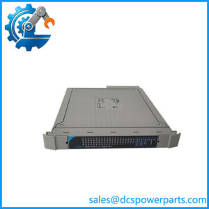
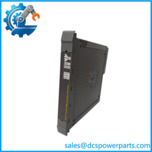
- T8110B — Trusted TMR processor module used in the chassis; performs the main safety application processing.
- T8111 — Trusted TMR processor variant used with the Trusted controller architecture.
- T8151B — Trusted communications interface used for Ethernet communication and engineering-system connectivity.
- T8153 — Trusted communications interface adapter providing physical communication connections associated with the T8151B.
- T8311 — Trusted expander interface module used when the controller system connects to CS300 expansion hardware.
- T8300 — Trusted expansion chassis for additional Trusted I/O capacity.
- T8270 — Trusted 24 VDC fan assembly used with the controller/expansion rack arrangement where required.
- T8240 — Trusted power shelf designed to accommodate multiple 24 VDC power packs.
- T8231 — Trusted 24 VDC power pack used in redundant Trusted system power arrangements.
- T8380 — Panel mounting kit that permits the chassis to be mounted from the rear of a panel.
Procurement Note
For a replacement, specify the complete chassis identification and document the existing system configuration before ordering. At minimum, record the installed processor modules, I/O/interface modules, communication interfaces, power arrangement, chassis revision, and Trusted software/firmware release.
For a used or surplus chassis, inspect the IMB backplane connectors, module guides, mounting hardware, grounding points, and connector condition. A chassis that passes a visual inspection is not necessarily suitable for a safety-system installation; post-installation diagnostics and the site’s required safety validation should be completed before returning the SIS to service.