Description
Product Overview
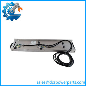
The Honeywell MC-GPRD02 is a power distribution assembly designed for Honeywell galvanically isolated field termination assemblies. Its role is to distribute 24 VDC power from the control-system power supply to compatible GI FTAs. Unlike a signal-processing module, it does not acquire analog or digital process signals. It supports the electrical infrastructure required by field termination hardware.
The assembly has two 6-pin input power connectors and eight 2-pin output connectors. The two inputs allow either a single power source or a dual-source arrangement. Each output provides 24 VDC to a compatible GI FTA through its own power cable. Honeywell documentation describes individually fused power distribution, making the MC-GPRD02 an important part of the field-side power architecture.
The 51304644-175 version is the CE-compliant, conformally coated version of the MC-GPRD02. This distinction matters when maintaining older cabinets: the -150 and -175 suffixes identify different compliance and coating configurations, not interchangeable cosmetic options. Cable selection, cabinet location, grounding, and power-source redundancy must be checked against the installed system design. For replacement procurement, confirm the complete part number and inspect all power connectors and fuse positions before installation.
Product Introduction (Non-Templated)
A galvanically isolated FTA installation can require more 24 VDC distribution capacity than the standard IOP-to-FTA power connection provides. The MC-GPRD02 addresses that requirement by supplying multiple compatible GI FTAs from a dedicated distribution assembly.
A replacement should be checked as part of the complete power circuit, not as an isolated board swap. Verify both incoming power paths, the eight outgoing connections, the specified cable types, and the fuse condition. Incorrect cable selection or an incomplete redundant feed can leave an FTA without its intended power arrangement.
Key Technical Specifications
| Parameter | Value |
|---|---|
| Product Model | MC-GPRD02 |
| Part Number | 51304644-175 |
| Manufacturer | Honeywell |
| Product Type | GI Power Distribution Assembly |
| Hardware Category | Field Termination Assembly power accessory |
| System Family | Honeywell High-Performance Process Manager / related I/O architecture |
| Isolation Classification | Galvanically isolated FTA power distribution |
| Input Power | 24 VDC |
| Input Connectors | 2 × 6-pin power connectors |
| Output Connectors | 8 × 2-pin power connectors |
| Output Function | 24 VDC distribution to compatible GI FTAs |
| Output Protection | Individually fused outputs |
| Power Source Arrangement | Single-source or dual-source |
| Compliance Version | CE-compliant |
| Coating | Conformal-coated |
| Mounting | FTA mounting channel |
| Mounting Dimensions | Same mounting dimensions as an A-size FTA |
| Output Channel Count | 8 |
| Communication Protocol | Not applicable |
| Firmware | Not applicable |
| Operating Temperature | Not verified for this assembly |
| Maximum Output Current | Not verified; confirm fuse ratings and system load documentation |
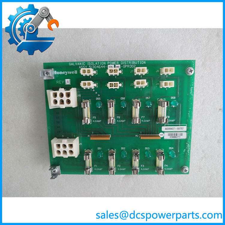
MC-GPRD02 51304644-175
Major Features and Advantages
Dedicated 24 VDC distribution for GI FTAs
Galvanically isolated FTAs have higher 24 VDC power requirements than standard FTAs. The MC-GPRD02 provides a dedicated distribution point instead of relying solely on power delivered through the IOP-to-FTA cable.
Eight individually fused output connections
The assembly provides eight 2-pin output connectors. Honeywell documentation specifies individually fused 24 VDC feeds, allowing the power distribution arrangement to be organized by FTA connection. Fuse ratings should be verified from the applicable hardware documentation before replacement.
Dual-source power input
Two 6-pin input connectors support either a single-source or dual-source power arrangement. Where redundant feeds are used, both power cables and their upstream sources must be checked. Two connectors alone do not prove that the cabinet is configured for effective redundancy.
CE-compliant, conformally coated version
The -175 suffix identifies the CE-compliant part number for the conformally coated MC-. The corresponding non-CE part number is 51304644-150. Do not substitute one suffix for the other without checking the cabinet’s compliance and configuration requirements.
Cabinet mounting flexibility
The Honeywell planning manual describes the power distribution assembly as having the same mounting dimensions as an A-size FTA. It can be mounted on horizontal or vertical FTA mounting channels, subject to the specified spacing and cable-routing requirements.
Defined cable and load limits
The manual specifies power-cable constraints, including a 12 A limit for the applicable daisy-chained input cable arrangement under the stated single-cable-failure assumption. Output cable length and current also have limits. These values must be applied to the actual cable type and wiring arrangement, not treated as a universal rating for every output.
Related Products
These components are associated with the same Honeywell I/O and FTA hardware environment. They are not direct replacements for the MC-.
- MU- – Related GI power distribution assembly in the non-conformally-coated configuration.
- MC-TDPR02 – Digital input power distribution assembly.
- MC-GAIH13 – GI high-level analog input / smart transmitter interface FTA.
- MC-GAIH14 – GI high-level analog input / smart transmitter interface FTA with auxiliary and high-voltage output functions.
- MC-GAIH83 – GI high-level analog input / smart transmitter FTA with crimp terminals.
- MC-GAIH84 – GI FTA with auxiliary and high-voltage output functions and crimp terminals.
- MC-GLFD02 – Combiner panel.
- MC-GMAR52 – Marshalling panel.
- MU-KDPRxx – Power cable family used to connect the power system to the distribution assembly.
- MU-KGPRxx – Power cable family used between the distribution assembly and compatible GI FTAs.
Frequently Asked Questions
Q1: What is the function of the Honeywell MC-?
It distributes 24 VDC power to compatible galvanically isolated FTAs. It is a power distribution assembly, not a pulse input module or a process signal-processing card.
Q2: How many FTA power connections does it provide?
The documented design has eight 2-pin output connectors. Each output supplies 24 VDC to a compatible FTA through the specified cable arrangement.
Q3: Does the MC- support redundant power?
Yes. It has two 6-pin input power connectors and supports either a single-source or dual-source arrangement. Actual redundancy depends on the cabinet wiring, independent upstream supplies, and cable configuration.
Q4: What is the difference between 51304644-150 and 51304644-175?
Both correspond to the MC-. The -150 is the non-CE part number, while -175 is the CE-compliant part number for the conformally coated version. Match the installed cabinet requirements before ordering.
Q5: Can I hot-swap the MC- while the system is running?
Do not assume live replacement is permitted. The available documentation establishes its power distribution function but does not establish a general hot-swap procedure for this exact assembly. Follow the site’s approved isolation and maintenance procedure, and verify the effect on every FTA supplied by the assembly before disconnecting it.
Q6: Does the MC- require firmware v3.1?
No firmware requirement has been identified. The MC- is a power distribution assembly, not a programmable controller or communication processor. Compatibility is determined by its hardware configuration, power connections, FTA type, and system installation.
Q7: What should be tested before installing a replacement?
Inspect the two input connectors, eight output connectors, fuse positions, board condition, and terminal integrity. Verify the 24 VDC input arrangement and output voltage under the intended load. If the installation uses redundant feeds, test both paths independently and confirm the connected FTAs receive the intended power.
Procurement and Compatibility Note
For a replacement order, specify the complete part number MC- / 51304644-175. Request clear photographs of the product label, connector side, fuse area, and PCB revision. Confirm that the unit is the CE-compliant conformally coated version, not the -150 variant.
The key procurement risk is not firmware compatibility; it is matching the cabinet’s power distribution and FTA wiring. Verify the two incoming feeds, output cable family, fuse ratings, and connected GI FTA load before putting the assembly into service.