Description
Key Technical Specifications
| Parameter | Specification |
|---|---|
| Manufacturer | HIMA |
| Model | X-DO1201 |
| Part Number | 985210204 |
| Product Family | HIMax |
| Product Type | Safety Digital Output Module |
| Output Channels | 12 |
| Output Signal | 24 VDC |
| Output Type | P-switching / sourcing output |
| Maximum Current | Up to 0.5 A per channel |
| Channel Isolation | Galvanic/optical isolation |
| Isolation Rating | Approximately 500 VAC |
| Diagnostic Functions | Short circuit, overload, wire-break/status monitoring |
| Typical Response | Approximately 1 ms |
| Operating Temperature | Approximately -25°C to +70°C |
| Protection | IP20 |
| Installation | HIMax rack / modular safety-system installation |
| Safety Application | SIS, ESD, BMS, process safety |
Available technical listings consistently identify X-DO1201 / 985210204 as a HIMA HIMax digital output module, although secondary listings contain conflicting channel-count and response-time information. The more consistent references identify 12 channels, 24 VDC operation, and up to 0.5 A per output.
For procurement, I would treat the exact nameplate and HIMA documentation for the installed system as authoritative rather than relying on generic reseller specifications. That matters with safety I/O.
Application Scenarios & Pain Points
A safety output module is usually noticed only after something refuses to actuate—or after a diagnostic system reports an output-channel fault. In a refinery or gas plant, the wrong replacement can turn a straightforward maintenance job into a proof-test problem.
- Emergency Shutdown Systems: Drives shutdown solenoids, interposing relays, and other discrete safety actuators where output behavior is supervised.
- Burner Management: Suitable for discrete commands associated with burner shutdown and permissive logic, provided the complete safety design approves the load.
- Process Safety Systems: Used for binary safety commands in chemical, petrochemical, and power-generation applications.
- Valve and Relay Control: The 24 VDC outputs can interface with field switching devices within the specified current and wiring limits.
Field note: If one channel reports a fault while the others operate normally, do not immediately condemn the entire module. Check the field load, fuse arrangement, terminal wiring, and output device first. A shorted solenoid can make a healthy output channel look defective.
Brief Field Case
During an emergency maintenance replacement, an output module may be electrically identical yet still require verification against the configured HIMax application. A technician should record the existing channel assignments and field wiring before removal, then perform the appropriate safety-system verification after installation.
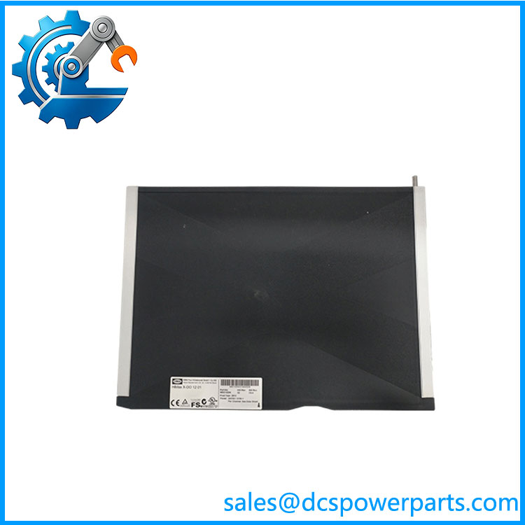
X-DO1201-985210204
Related Products
- HIMA X-DO1201 985210204 — The exact subject module, providing safety-related digital outputs for the HIMax platform.
- HIMA X-DI1601 985210222 — HIMax digital input module. It handles discrete field status signals rather than output commands, making it complementary to X-DO1201.
- HIMA X-DO2401 985210203 — Related HIMax digital output model with a different channel density. It should not be substituted solely because both are digital-output modules.
- HIMA X-SB01 985210207 — HIMax system-bus module used for system-level communication rather than field digital output.
- HIMA X-FAN1003 993201013 — HIMax chassis cooling component. It supports the rack environment but has no I/O-channel function.
- HIMA F8652X 984865265 — HIMax central processing hardware. It provides controller functionality while X-DO1201 handles field output channels.
- HIMA F3236 — HIMA safety digital input module from another product family. Its input function makes it complementary rather than a direct replacement.
- HIMA F3330 984333002 — HIMA safety digital output module from the F-series family. Similar in basic signal role, but it belongs to a different hardware architecture and requires system-specific compatibility verification.
- HIMA F7553 984755302 — HIMA I/O bus coupling hardware. It serves a communication/interface role rather than replacing an X-DO1201 output card.
The Engineer’s Guide: Field Pitfalls to Avoid
WARNING 1 — Do not treat every HIMA digital-output card as interchangeable.
X- belongs to the HIMax architecture. Older F-series output modules may have similar signal functions but different system interfaces and safety configurations.
How to avoid it: Match the complete HIMA model and part number, then verify the installed controller/rack documentation before substitution.
WARNING 2 — Verify the field load before energizing an output.
The commonly documented maximum is approximately 0.5 A per channel.
How to avoid it: Check the connected solenoid, relay coil, actuator interface, and any inrush characteristics. A coil that exceeds the channel rating can create repeated overload diagnostics or damage the output circuitry.
WARNING 3 — Do not skip the post-replacement safety verification.
A module that powers up and shows normal LEDs has not necessarily passed the required safety acceptance procedure.
How to avoid it: After replacement, follow the site’s approved procedure for:
- Module identification.
- Controller/rack diagnostics.
- Channel status verification.
- Field-loop verification.
- Output functional test.
- Proof-test or safety validation requirements.
- Return-to-service authorization.
In a SIS, “the LED is green” is not a sufficient acceptance criterion.
Frequently Asked Questions (FAQ)
What is HIMA X- 985210204?
X-, part number 985210204, is a HIMA HIMax safety digital output module. It provides discrete 24 VDC output signals to external field devices and is intended for safety-related automation applications.
How many outputs does the X- have?
The more consistent technical references identify 12 digital output channels.
Some online listings give contradictory specifications, so for a safety-system purchase I recommend confirming the physical nameplate and applicable HIMA documentation before accepting a shipment.
What voltage does HIMA X- use?
The documented operating/output signal is 24 VDC. The commonly published maximum channel current is approximately 0.5 A per output.
The actual field load still needs to remain within the approved system and wiring limits.
Is X- a SIL 3 module?
It is used as a safety I/O component within HIMA safety-system architectures, and secondary technical references identify it with IEC 61508 SIL 3 applications.
The important engineering point is that a SIL rating applies to the complete safety function and configured system, not merely to a loose replacement card. The actual safety lifecycle documentation for the installation controls.
Can I replace X- with X-DO2401?
Do not assume direct interchangeability. Although both are digital-output modules in the HIMax family, their channel density and hardware configuration differ.
Before substitution, verify:
- Part number
- Channel allocation
- Rack position
- Firmware/system compatibility
- Terminal arrangement
- Safety configuration
- Application logic
- Proof-test requirements
What should I check before installing a replacement X-?
Check the 985210204 identification, physical condition, connector integrity, and storage history first. Then compare the replacement with the existing system configuration.
For a used spare, inspect the connector pins carefully—no oxidation, bent contacts, cracked housing, or contamination. After installation, perform the site’s prescribed safety and functional checks rather than relying solely on a power-up indication.
What should I request when purchasing a refurbished HIMA X-?
For a production SIS spare, request:
- Exact X- / 985210204 identification.
- Clear nameplate photographs.
- PCB and connector photographs.
- Channel-output test report.
- 24 VDC output verification.
- Diagnostic-function test where supported.
- Connector inspection.
- Firmware/revision information when available.
- Traceable condition statement.
- Warranty documentation.
For safety-system inventory, tested functionality and traceability are more valuable than a generic “tested” label.