Description
Product Overview
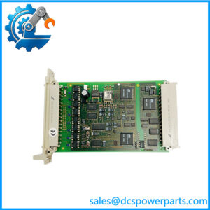
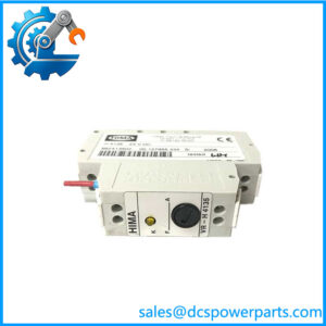
H 6200A is a DIN-rail analogue repeater power supply. One 4–20 mA signal arrives from a transmitter sitting in a hazardous area, and two mutually redundant 4–20 mA signals leave on the safe side, with the input and both outputs galvanically isolated from one another. HIMA’s own designation for the device type is Analog Repeater Power Supply, German Analogspeisetrenner — “power supply separator” — and the word power is there for a reason: the field loop is energised from the safe side through the barrier, at 15 V and 20 mA, so a two-wire transmitter in the Ex area needs no local supply at all.
Around that core sit three properties that decide whether a plant can use the device at all. It carries the [Ex ia] IIC marking with published entity parameters — Uo 27.9 V, Io 91.9 mA, Po 641 mW, Co 84 nF, Lo 2 mH against Um 250 V — plus a Zone 2 marking of Ex nA II T4 for the safe-side installation. It is certified as a safety-related device under TÜV 968, assessed against IEC 61508 and EN ISO 13849-1. And it is built to pass HART in both directions, which is the requirement that quietly disqualifies most general-purpose barriers once a plant wants to configure and diagnose its transmitters through the same pair of wires.
The problem it solves is specific. A single pressure or level transmitter often has to feed two consumers: the safety function that trips a valve, and the control system that trends and controls. Fitting a second transmitter doubles the intrusion into the process, doubles the impulse line work and doubles the calibration record. The H 6200A instead repeats one measurement into two isolated outputs, and its internal diagnostics can switch off one output or the whole converter when a fault is detected — so a failing channel does not have to take both consumers with it.
Two naming traps surround this part. The first is internal to HIMA: the HIMax safety controller’s processors are the X-CPU 01 and X-CPU 31, and no HIMax CPU is called H 6200-something, so descriptions that present this as a redundant SIL 4 controller with 512 MB of DDR3 are describing a product that does not exist. The second is about scope: this is an interface device that sits in front of the I/O module, not an I/O module, and it holds no application program, no configuration and no system identity. Its entire job is to move one analogue value across an Ex boundary twice, safely, and to keep powering the field loop while doing it.
Technical Specifications
| Parameter | Value |
|---|---|
| Model | H 6200A |
| Manufacturer | HIMA Paul Hildebrandt GmbH, Germany |
| Product type | Analogue repeater power supply, intrinsic-safety barrier |
| Signal path | One 4–20 mA input, two redundant 4–20 mA outputs |
| Isolation | Galvanic, input to outputs |
| Transmitter supply | 15 V DC / 20 mA for the hazardous-area loop |
| Protocol transparency | HART, receive and transmit |
| Basic accuracy | ±0.2 % of span |
| Temperature coefficient | ±0.1 % per 10 °C |
| Supply voltage | 24 V DC, approx. 140 mA |
| Ex marking | [Ex ia] IIC; Zone 2 Ex nA II T4 |
| Entity parameters | Uo 27.9 V, Io 91.9 mA, Po 641 mW, Co 84 nF, Lo 2 mH |
| Maximum safe-circuit voltage | Um 250 V |
| Ambient temperature | 0 °C to +60 °C, storage −40 °C to +85 °C |
| Mounting | 35 mm DIN rail |
| Dimensions and mass | 35 × 99 × 114.5 mm, 200 g |
| Standards | IEC 61508, EN ISO 13849-1 (TÜV 968), ATEX 7064 / 7065 X |
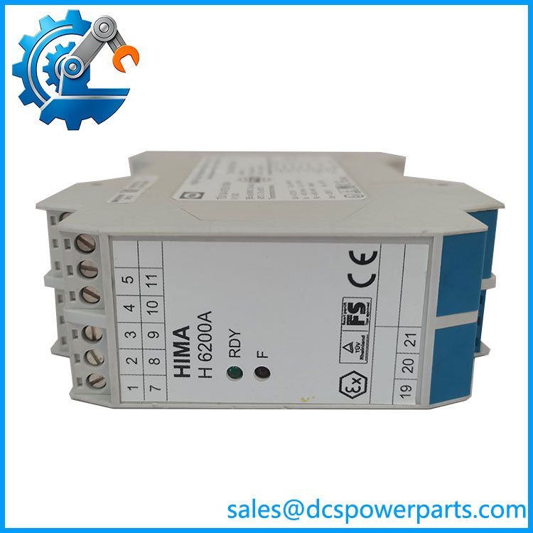
H6200A
Key Features and Advantages
One measurement, two consumers: the dual output is the whole point. A transmitter in Zone 1 feeds the trip logic and the control system at the same time, from the same impulse line, through the same calibration. On a revamp where a new SIS has to take over a measurement that the DCS already owns, this is the difference between one engineering package and two.
Power from the safe side: the 15 V / 20 mA transmitter supply output means the field device is energised through the barrier. There is no local 24 V feed in the hazardous area, no additional Ex-approved supply, no second pair of terminals to maintain — and the same output will power a passive resistance sensor, which is why the device is accepted as a measuring transducer and not merely as a signal splitter.
Diagnostics that act instead of just indicating: the module monitors its own health and can disable one output or shut the whole channel down when it detects a fault. In a split-architecture installation that behaviour is a design input, not a footnote — it determines whether a barrier failure degrades one consumer or both, and it belongs in the cause-and-effect discussion rather than in the spare parts list.
Entity parameters published, not implied: Uo, Io, Po, Co and Lo are the numbers a hazardous-area designer actually works with, because the permitted cable capacitance and inductance on the field side come out of them. A barrier whose Co and Lo budget is spent on 60 metres of cable leaves nothing for the transmitter’s own internal values, and no amount of correct part numbering fixes that.
HART that survives the barrier: configuration and diagnostics reach the transmitter through the same loop, so a technician with a handheld or an asset-management system can work at the marshalling cabinet instead of walking to the device. Barriers that attenuate HART work perfectly as signal isolators and fail as maintenance tools.
Small enough to fit the cabinet you already have: 35 mm wide, 99 mm deep, on standard DIN rail, at 200 g. Retrofitting Ex isolation into a crowded marshalling cabinet is usually a space question before it is a technical one, and this format answers it.
Applications
Refinery and petrochemical ESD loops: pressure, level and flow transmitters in Zone 1 or Zone 2 feeding both the safety trip and the basic control system, where splitting the measurement at the barrier avoids a second intrusion into the process.
Fire and gas detection circuits: analogue gas and flame transmitters in hazardous areas whose 4–20 mA output must reach the F&G controller while remaining available for trend and diagnostic purposes.
Tank farm and loading terminal level measurement: guided-wave radar transmitters with internal zener barriers, a case HIMA documentation addresses directly by recommending its HART analogue isolator ahead of the analogue input module when signal spikes or undefined levels are a concern.
Gas metering and pressure-reducing stations: custody-adjacent transmitters that must be configured and verified remotely through HART while their output is consumed by two independent systems.
Boiler and burner management: 2-wire transmitters on the firing side whose signals are shared between the burner management logic and the plant historian or control layer.
Water and wastewater chemical dosing: transmitters in areas classified for flammable gas or toxic media, powered from the safe side and repeated to both the dosing controller and the SCADA layer.
Test and calibration benches: repeaters used to reproduce a two-output field loop for verifying SIS input cards without energising a real hazardous-area installation.
Related Products
X-AI 32 01 — HIMax 32-channel 4–20 mA analogue input with line monitoring, the module the safe-side output typically feeds. X-AI 32 01 A — revised HIMax analogue input of the same family, SIL 3 with line monitoring. X-AI 16 51 — HIMax 16-channel analogue input with galvanic isolation, temperature and Pt100 functions. X-HART 32 01 — HIMax HART communication module providing 32 modems for the analogue input and output modules. X-FTA 007 02L — redundant field termination assembly specified for the X-AI 32 01 / 32 02 analogue inputs. F 6217 — HIQuad 8-channel analogue input module for which HIMA documentation names the HART analogue isolator as the front-end solution. F 6215 — HIQuad 8-channel current, voltage and Pt100 input module of the same platform. H 7015A — HIMA terminal module used with the HIQuad X I/O wiring, a companion in the same marshalling concept. H 7018 — terminal module mating with H 7015A, same terminal family, different wiring arrangement. MTL 4500 series — comparable intrinsic-safety repeater power supplies from another vendor; functional equivalent, not a drop-in replacement.
Installation and Maintenance
Before installation: confirm the field device’s entity values against the barrier’s published Uo, Io, Po, Co and Lo, then calculate the cable’s capacitance and inductance and check that the margin which remains still covers the transmitter. Verify the hazardous-area classification, because the [Ex ia] IIC marking and the Zone 2 Ex nA II T4 marking apply to two different sides of the same device, and verify that the safe-side circuit does not exceed Um 250 V. Check that the 24 V DC feed is from a source appropriate to the safety function it serves, and confirm the DIN rail space and the 35 mm width before pulling wire. Record the existing channel’s role — which consumer sits on output one and which on output two — so the replacement is restored to the same split.
Maintenance practice: the device has no adjustments to drift, so periodic work centres on the loop rather than the box. Perform the calibration check at the interval your verification programme sets — the published Russian verification procedure for this type uses three years — and compare both outputs against the same input, because the failure mode worth catching is a divergence between output one and output two rather than a shift affecting both. Keep the HART path proven by reading the transmitter’s tag and range through the barrier at each proof test; a barrier that has lost HART transparency will still pass 4–20 mA and hide the loss until someone needs to configure the device. On replacement, re-check the Ex entity calculation if the cable or the transmitter has changed since the original design, and confirm diagnostic behaviour is as the cause-and-effect study assumes.
Warranty and Quality
Every H 6200A is supplied as HIMA’s analogue repeater power supply with the Ex and safety documentation identity confirmed — [Ex ia] IIC, Zone 2 Ex nA II T4, TÜV 968 — because the designation is what the certification refers to, and a device sold without it cannot be entered into an Ex register. Units are inspected for terminal condition, housing integrity and DIN-rail clip function, and are checked for correct channel behaviour where a test loop is available. They carry a 12-month repair, replacement or refund commitment. Support covers the questions this device really generates in the field: checking entity parameters and cable Co/Lo budgets before an Ex loop is energised, distinguishing a barrier fault from a transmitter fault when both outputs read low, preserving HART transparency through replacement, and confirming that the part is the signal interface it claims to be rather than the controller some listings describe.
免费
今天 16:43