Description
Product Overview
GVC714A101 is the electronic layer that stands between an ABB converter’s control electronics and the power device that actually switches megawatts. In an ACS5000 or ACS6000 drive the switching element is a press-pack IGCT — a hard-driven, snubberless device that needs a gate current pulse of a very specific shape to turn on, and an even more demanding reverse gate current to commutate off. Neither can be produced by a control board sitting at safe potential on the other side of a cabinet. The gate unit exists because that pulse must be generated at the potential of the device it drives, inches from the gate, with the lowest inductance the layout can achieve.
The board’s designation and its order code are two different things and the trade routinely blends them. GVC714A101 is the board designation, the string silkscreened on the PCB; 3BHE024415R0101 is the ABB order code used to buy it. The code prefix is informative: 3BHE belongs to ABB’s power-electronics control board family, alongside gate units, phase interface boards and converter control electronics, while 3BHB codes identify the power semiconductor assemblies themselves. Buying “3BHE024415R0101” and expecting a valve assembly — as one page on the web describes it — is the consequence of not knowing that split. The gate unit is one board; the valve is the mechanical and electrical assembly that holds the devices, their heatsinks, the clamping and the cooling connections.
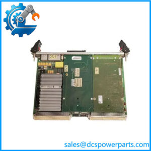
Functionally the board does three jobs and does them in the hardest electromagnetic environment in the plant. It receives the firing command optically from the converter control, so the command and the status feedback cross the high-voltage isolation barrier as light rather than as copper, which is the only practical way to carry a signal across several kilovolts while a phase leg switches. It converts that command into the gate pulse for one press-pack IGCT — turn-on and turn-off — with the very high di/dt and the low gate-circuit inductance the device requires for safe, snubberless commutation. And it watches the device: desaturation and on-state behaviour are monitored locally, so a device that has begun to fail is detected and shut down in a controlled manner at board level, with the fault reported back to the converter control over the same optical path, instead of being allowed to develop into a converter trip that takes the whole drive — and possibly a production line — down.
That third function is the commercial reason these boards are kept as strategic spares rather than ordered after a failure. A degrading gate unit does not announce itself. It shows up as sporadic overcurrent or desaturation trips under load, sometimes only on one phase leg, sometimes only at high ambient temperature, and it is frequently misattributed to the IGCT, to the motor, or to the process. Because each phase leg carries several devices and each device has its own gate unit, a marginal board can hide behind its neighbours for months, and a fault that looks like a device failure can be a driver failure — which is also why a failed IGCT almost always justifies testing its gate unit before the replacement device is trusted.
Matching is the discipline this part demands. The board is built for the 5SHX and 5SGX IGCT families, and which build of the board is correct depends on the exact device and on the converter’s documentation rather than on the order code alone. Within a phase leg, ABB’s practice is to keep boards of the same hardware build, because different builds carry different soft-shutdown timing; mixing builds across devices that commutate together is a way to obtain inconsistent protection behaviour in exactly the situation where consistency matters. And the device numbers themselves are a trap: 5SHX1006H0003 and 5SHX1060H0003 differ by transposition, not by a digit, and refer to different device ratings. Reading a nameplate is not optional here.
There is no published board-level data sheet for this part, and the trade responds to that absence by inventing one. The same page that correctly calls it an IGCT gate drive board also categorises it as a “DCS IO Card”. Others describe CANopen and Modbus RTU interfaces, a 5 A output, IP20 protection, a 120 × 80 × 35 mm housing; or a 1 GHz processor with 1 GB RAM and 16 analogue plus 16 analogue output channels; or an operating system called “ABB ControlLogix”; or a 100–240 VAC supply with DeviceNet and Profinet. None of that exists on this board. It has one optical command interface, one gate output to one device, one auxiliary DC supply, and no fieldbus, no I/O channels, no enclosure rating and no operating system. The values that are genuinely documented are modest and are listed as such below; everything else belongs to the converter documentation, not to a marketplace description.
Technical Specifications
表格
| Parameter | Value |
|---|---|
| Board designation | GVC714A101 |
| ABB order code | 3BHE024415R0101 |
| Manufacturer | ABB, power electronics (Turgi, Switzerland lineage); manufacturing origin varies by build — read the label |
| Product type | IGCT gate drive unit (gate drive board), not an I/O card and not a valve assembly |
| Host platforms | ACS5000 and ACS6000 medium voltage IGCT drives; other high-power IGCT converters of the same generation |
| Power device family | ABB 5SHX and 5SGX press-pack IGCTs; exact device to be confirmed against the drive nameplate (e.g. 5SHX1006H0003, 5SGX1060H0003 — note 5SHX1060H0003 is a different device) |
| Gate pulse interface | Fibre-optic link to and from the converter control (AC 800PEC based); command and status cross the HV isolation barrier optically |
| Output function | Turn-on and turn-off gate drive for one IGCT of one phase leg; low-inductance gate connection at device potential |
| Monitoring and protection | Desaturation / overcurrent detection, soft shutdown at board level, device status and fault feedback to the converter control, board fault indication |
| Auxiliary supply | Low-voltage DC auxiliary from the converter control compartment (24 VDC class; confirm the actual feed at the cabinet) |
| Mounting | Plug-in board on the IGCT power stack / converter rack inside the earthed cabinet; one per gate-driven device |
| Cooling | Cabinet ventilation; the board has no separate cooling circuit and no heatsink of its own |
| PCB reference | 5SXE07-0164 is quoted as the internal PCB code — verify on the board silkscreen before cross-referencing |
| Physical | Dimensions and weight not published consistently (published figures conflict); confirm by measuring the original board — typical handling weight around 1 kg |
| Documentation status | No ABB board-level data sheet; parameters derive from the host drive’s installation and service manuals |
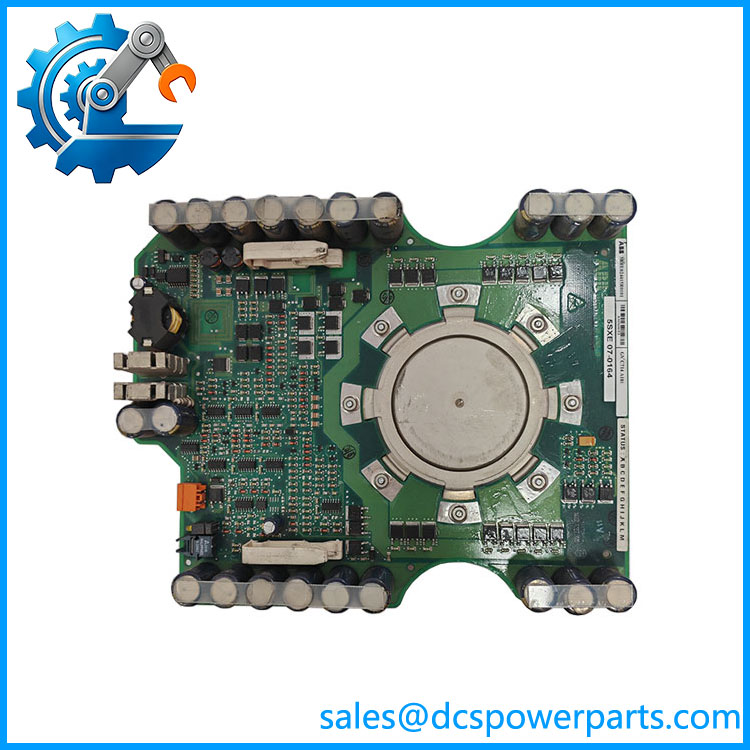
GVC714A101
Key Features and Advantages
Gate pulse at device potential: the board sits on the power stack, not in the control compartment, because a gate pulse of the required amplitude and di/dt cannot be transmitted any distance without losing its shape. Locating the driver at the gate is what makes snubberless IGCT commutation practical, and it is why this board is a power-stack component rather than an electronics-rack component.
Optical command and feedback across the isolation barrier: firing commands and device status travel as light. In a cabinet where a phase leg switches several kilovolts with nanosecond edges, a copper command link would be an antenna; the optical link removes the coupling path entirely and keeps the control electronics referenced safely away from device potential. It also means the fibre faces are part of the maintenance routine — contamination on an optical face produces gate faults that look like electronics failures.
Local desaturation supervision rather than remote guessing: the board measures the device’s behaviour where the device is, and decides locally. A press-pack IGCT’s characteristic failure mode is a short, so an abnormal on-state has to be caught fast and handled in a defined sequence — controlled shutdown and a fault report to the converter control — rather than discovered later as a DC-link overcurrent event that takes the whole converter out.
Board-level soft shutdown as converter protection: shutting down a device cleanly at its own driver limits the energy the failure can dissipate and gives the converter control time to isolate the leg. The engineering value is measured in what does not happen: no exploding device, no damaged neighbours, no contaminated cooling circuit, no multi-week outage to clean a valve.
One board per device, and the discipline that follows: because each gate-driven device has its own driver, a phase leg contains several of these boards that must behave identically. Keeping the same hardware build across a leg — the point ABB’s own spares guidance makes about differing soft-shutdown timing — is a configuration control task, and recording each board’s build and fibre assignment is part of it.
A diagnostic signature worth learning: degradation presents as sporadic overcurrent or desaturation trips under load, often on one leg and often temperature-correlated, before it presents as a hard trip. Treating that pattern as an IGCT problem and replacing the device without testing its driver is the expensive way to learn this board’s failure mode.
Numbering literacy as a purchasing safeguard: GVC714A101 is the board, 3BHE024415R0101 is the order code, 5SXE07-0164 is claimed as the PCB reference, and the IGCT is a separate 5SHX or 5SGX device with its own ratings. Four strings that appear together in listings and mean four different things — and the part that must match the drive is the combination, not any single string.
Honest limits: no fieldbus, no analogue or digital I/O, no IP rating, no processor, no operating system, no standalone function. This board works only inside an IGCT converter, is referenced to lethal potential, and cannot be bench-tested without the proper fixture and the converter’s own procedures.
Applications
ACS6000 drives in oil and gas: large gas compressors and pipeline boosters driven by multi-megawatt medium voltage converters, where a gate unit failure on one leg means an unplanned shutdown of a machine that is usually the reason the plant exists. Spares of this board sit in the warehouse for exactly that.
ACS5000 drives in mining and minerals: main ventilation fans, conveyor drives and mill drives, where the electrical environment is hot, dusty and vibration-heavy, and where the gate unit’s optical link is the reason its command signals survive at all.
Metals: rolling mill main drives and coilers, where gate timing across a phase leg translates directly into torque ripple and strip quality. A board that has drifted in its turn-off behaviour shows up as current imbalance and gauge variation long before it trips.
Marine and offshore propulsion: converter-fed propulsion and thruster drives, where redundancy is designed in and where a single gate unit is a known single point that the spares inventory is built around.
Power generation and test stands: grid-connected converters, static frequency converters for gas turbine starting, and dynamometer or test-bench drives that are cycled hard and therefore wear their gate units faster than a continuous-duty process ever would.
Water and wastewater, cement and pulp: large pumps, kiln drives and refiners where the drive runs continuously and the failure mode is a stopped process rather than a damaged product.
The recurring theme across all of these is that the board is never the subject of the maintenance decision — the drive is. GVC714A101 is ordered because a converter must come back, and the engineering question is always whether the board’s build and the device on the stack match the cabinet’s documentation.
Where it does not apply: any low-voltage drive, any IGBT-based converter, any ABB drive whose power section is not built from press-pack IGCTs, and any application expecting an I/O or communication module. The board has one job and one interface.
Related Products
GVC704AE01 / 5SHX1060H0001 — the sibling gate unit design for an adjacent IGCT build; same family, different device generation, and not a substitute without ABB confirmation. 5SHX1006H0003 — press-pack IGCT driven by this board in several ACS6000 configurations; confirm against the stack nameplate. 5SGX1060H0003 — the other IGCT family the board is built for; device selection determines which board build is correct. 5SHX1060H0003 — a different IGCT from 5SHX1006H0003 despite the near-identical string; the transposition is the trap. 3BHB020538R0001 — a 3BHB-family power assembly code frequently listed on the same pages; note that 3BHB denotes power hardware while 3BHE denotes the control board family to which this gate unit belongs. ACS6000 — the multi-megawatt IGCT drive platform this board serves, with multiple gate units per phase leg. ACS5000 — the higher-voltage IGCT platform of the same generation, sharing the gate unit approach. 5SXE07-0164 — quoted PCB-level reference for the board; treat it as a silkscreen cross-reference rather than an orderable part number.
Installation and Maintenance
Before installation: confirm three things before the cabinet is opened. First, that the board’s build matches the device on the stack and the position in the phase leg — ABB’s spares guidance is explicit that different builds carry different soft-shutdown timing and that a leg should carry consistent builds. Second, that the fibre assignment is recorded: which optical channel fires which device, and which returns status. Third, that the replacement is a genuine GVC714A101 / 3BHE024415R0101 and not a board described as an “IGCT module” or as a valve assembly by a listing that did not know the difference. Then de-energise, discharge the DC bus, and verify the discharge with a calibrated meter — the gate unit is referenced to the potential of the device it drives, and that potential is lethal.
Installation: record the hardware build, the position, and the fibre routing before removal; cap and clean the optical connectors, because a contaminated face is a classic cause of spurious gate faults after a perfectly good board change. Fit the replacement on the stack, reconnect the auxiliary supply and the optical channels, and verify the gate pulse with the converter inhibited before any device is allowed to switch. Confirm that the status and fault feedback actually arrives at the converter control, and only then return the drive to service. If an IGCT in the leg has failed, inspect and test the associated board as well: a failed device frequently damages its driver, and a driver that damaged its device will do it again.
Maintenance: treat the boards as a matched set per leg rather than as individual spares — record build, position and fibre channel for each, and replace in matched pairs or full legs where the documentation calls for it. Keep the cabinet’s ventilation and filter condition under review: the board has no cooling circuit of its own, so its thermal life is the cabinet’s thermal life. Log every desaturation or overcurrent event with the leg, the load and the ambient at the time; that log is what turns a sporadic trip into a diagnosed gate unit instead of a replaced IGCT. Keep fibre connectors, spare caps and cleaning materials in the spares kit, and hold at least one board per converter type — the lead time on this part is not a lead time a running drive can absorb.
Warranty and Quality
Every is supplied as an ABB IGCT gate drive unit for ACS5000 and ACS6000 converters, identified by board designation and order code 3BHE024415R0101, with the silkscreen reference checked on the board itself rather than taken from a listing. Because ABB publishes no board-level data sheet for this part, and because the market describes the same string as everything from a DCS I/O card to an entire valve assembly, verification is done physically: build marking, fibre connector condition, gate output termination, auxiliary supply connector, evidence of prior rework, and confirmation that the board is not a device-level part number in disguise. Units are checked and tested before dispatch; where a converter bench or a gate-unit test fixture is available the gate pulse and the fault feedback path are exercised. A 12-month repair, replacement or refund commitment applies. Technical support addresses the questions this part actually raises: what distinguishes a gate unit from a valve assembly, why 3BHE and 3BHB belong to different families, why builds must match within a phase leg, why 5SHX1006H0003 and 5SHX1060H0003 are not interchangeable, and why a sporadic desaturation trip should be investigated at the driver before the device is condemned.
免费
今天 15:04