Description
Key Technical Specifications
| Parameter | Specification |
|---|---|
| Product model | GESADA-1 |
| Manufacturer | GESPAC |
| Product category | Analog input/output board |
| Bus type | Industrial ISA |
| ADC input channels | Up to 16 single-ended or 8 differential |
| DAC output channels | 4 |
| ADC resolution | 10-bit |
| DAC resolution | 10-bit |
| Documented analog input range | ±5 V in the GESPAC telemetry configuration |
| Configurable input ranges | ±10 V, ±5 V, or 0–10 V in the documented driver reference |
| Documented analog output range | ±10 V in the GESPAC telemetry configuration |
| Output range selection | Hardware jumper and software configuration dependent |
| Host interface | ISA bus, I/O-mapped access |
| External wiring | Separate termination cards used in the documented telemetry system |
| Operating temperature | Not verified |
| Supply voltage | Not verified as a complete board power specification |
| Protection rating | Not verified |
The available documentation describes multiple hardware and software configurations. The supported input range, differential mode, and output range must match the actual board’s jumpers, options, and driver settings. The ±5 V input and ±10 V output values above refer to a documented GESPAC telemetry setup, not a guarantee for every board configuration.
Major Features and Advantages
Combined analog acquisition and output
The GESADA-1 combines ADC and DAC functions on one board. It can acquire analog measurements and generate analog command signals without requiring separate acquisition and output boards for every channel group. The documented configuration provides up to 16 input channels and 4 output channels, with 10-bit conversion resolution.
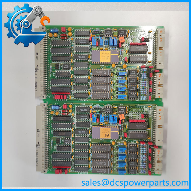
GESADA-1
Flexible input configuration
The software reference documents 16 single-ended or 8 differential input configurations. Differential mode requires the appropriate board option, and the multiplexer configuration must match the hardware jumpers. The selected voltage range must also match the board’s physical configuration. Incorrect settings can produce invalid readings or cause input signals to be interpreted incorrectly.
Analog command generation
The four DAC channels can generate analog output signals within the supported configured range. In the documented GESPAC telemetry application, analog outputs are used for equipment commands such as lighting and thruster control. That example illustrates a possible system role; it does not establish suitability for every industrial actuator or control loop.
Termination-card wiring
The documented telemetry system connects the GESADA board to separate termination cards, which provide field wiring connections. This arrangement helps separate the plug-in circuit board from the wiring interface and can make signal tracing and maintenance more manageable. Confirm the correct termination card and cable assembly before replacing the board.
Legacy software integration
The GESADA-1 is documented in an industrial ISA hardware reference with software driver blocks for analog input and analog output. The reference also notes limitations involving external trigger and interrupt propagation. Existing applications should therefore be checked for driver support and timing dependencies before a replacement is commissioned.
Application Scenarios and Common Pain Points
Potential applications include:
- Telemetry systems: Converting sensor signals into digital measurements and producing analog command outputs.
- Analog sensor acquisition: Reading compatible voltage-output sensors, provided their signal ranges and grounding arrangement match the board configuration.
- Equipment command interfaces: Generating analog reference signals for compatible external devices.
- Legacy industrial computers: Maintaining existing ISA-based hardware where the original software and wiring remain in service.
- Control-system restoration: Replacing a failed analog interface while retaining the original host architecture.
Common problems include mismatched input ranges, incorrect jumper settings, unsupported differential mode, incorrect I/O base-address configuration, and termination-card wiring errors. The software reference explicitly ties the configured base address and voltage range to the hardware settings. Verify both before diagnosing the board as defective.
Related Products
These GESPAC products have related analog, digital, or system-interface functions. They are not direct substitutes unless the application and electrical requirements have been checked.
| Model | Function | Key distinction |
|---|---|---|
| GESADC-2 | 16-channel, 12-bit ADC | Analog input only; higher documented resolution |
| GESADC-12 | Analog-to-digital conversion board | Used in some GESPAC system configurations |
| GESDAC-2B | 8-channel, 12-bit DAC | Analog output only; more output channels and higher resolution |
| GESPIA-2A | 32-line digital I/O | Digital signals rather than analog conversion |
| GESPIA-4 | 64-line digital I/O | Separate digital interface board |
| GESMFI-1 | Multifunction interface | Combines serial I/O, PIA, and real-time clock functions |
| GESSBS-8 | GESPAC single-board computer | Host computer identified in the telemetry documentation |
The GESADC-2 and GESDAC-2B are useful comparison points when evaluating conversion resolution or separating input and output functions. Their channel counts and electrical behavior differ from the GESADA-1, so substituting either one requires a system-level review.
Engineer’s Guide: Three Checks Before Installation
1. Match the hardware configuration. Check the full model marking, board revision, installed options, and termination-card part number. Confirm whether the system uses single-ended or differential inputs.
2. Verify range and addressing settings. Compare the board’s jumpers and DIP switches with the application configuration. Do not apply ±10 V to an input configured for a lower range. Confirm the I/O base address and the selected ADC/DAC ranges before enabling field signals.
3. Test each channel with known signals. Validate representative ADC inputs against a calibrated source and verify DAC outputs with a suitable meter or test instrument. Check channel scaling, polarity, grounding, and output loading before returning the system to service.
Frequently Asked Questions
Q1. What does the GESPAC GESADA-1 do?
It is an analog input/output board that combines ADC and DAC functions. It supports measurement acquisition and analog command generation in compatible industrial computer systems.
Q2. How many analog channels does it have?
The documented configuration supports up to 16 single-ended or 8 differential analog inputs, plus 4 analog outputs. Differential operation depends on the board option and configuration.
Q3. What is the conversion resolution?
The ADC and DAC are documented as 10-bit. This is lower than the 12-bit conversion resolution listed for the GESADC-2 and GESDAC-2B comparison boards.
Q4. What voltage range does it support?
The GESPAC telemetry reference describes inputs from −5 to +5 VDC and outputs from −10 to +10 VDC. A separate software reference lists configurable input ranges of ±10 V, ±5 V, and 0–10 V. Verify the actual board’s hardware settings and application configuration before connecting signals.
Q5. Is it compatible with a modern PLC or DCS?
Direct compatibility should not be assumed. The GESADA-1 is documented as an industrial ISA board with I/O-mapped access. Integration with modern equipment may require a different host platform, custom interface hardware, or a system migration project.
Q6. What should be checked when buying a used board?
Confirm the exact model and revision, inspect connectors and components, verify any installed options, and request evidence of ADC and DAC testing. A listing that says “tested” should specify which channels and ranges were checked.
Q7. What are the warranty and lead time?
These depend on the supplier and the condition of the individual unit. Confirm stock status, test scope, warranty duration, dispatch timing, and return terms before placing an order.
Procurement recommendation: The is best treated as a legacy analog acquisition and output board whose configuration must be matched to the original system. Verify its jumper settings, input mode, voltage ranges, I/O address, and termination hardware before approving a replacement.