Description
Key Technical Specifications
| Parameter | Specification |
|---|---|
| Product model | VMIVME-2510B |
| Manufacturer / product lineage | VMIC / GE Fanuc / Abaco Systems |
| Product type | Digital input/output Megamodule |
| Bus interface | VMEbus |
| Digital I/O capacity | 64 bits |
| Port organization | Eight 8-bit ports |
| Port direction | Individually programmable in the TTL I/O configuration |
| Logic interface | TTL; optional open-collector output configuration |
| Output current capability | Up to 64 mA sink capability, as documented; confirm loading conditions |
| Data transfer widths | 8, 16, and 32 bits |
| I/O connectors | Two 64-pin DIN-type connectors |
| Addressing | Short I/O address mapping with board address switches |
| Built-in diagnostics | Online and offline test functions |
| Status indication | Front-panel Fail LED |
| Supply requirement | +5 VDC, maximum 3.786 A |
| Operating temperature | 0°C to +55°C |
| Storage temperature | −20°C to +85°C |
| Cooling | Convection |
| Relative humidity | 20%–80%, noncondensing |
These values come from the VMIVME-2510B product manual and supporting technical descriptions. The stated current capability is not a blanket guarantee that every output can drive every load continuously under all conditions. Review the manual’s output-current, thermal, and wiring limitations before designing the interface.
Major Features and Advantages
Eight independently configured I/O ports
The VMIVME-2510B organizes its 64 digital signal lines into eight 8-bit ports. In the TTL configuration, each port’s direction can be programmed individually. This allows a single board to handle a combination of digital inputs and outputs when the application requires both functions.
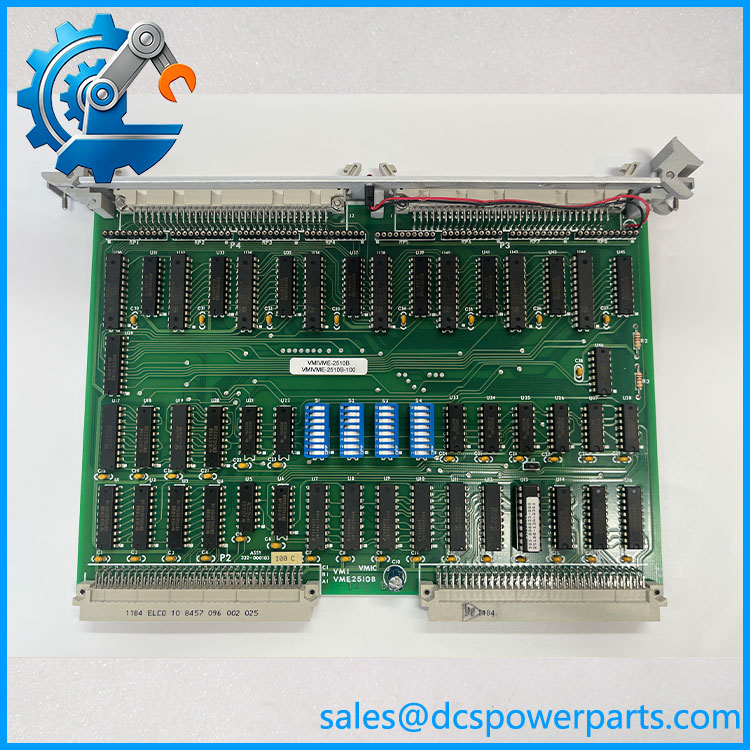
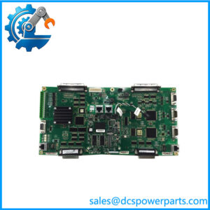
VMIVME-2510B
VMEbus integration
The board is designed for VMEbus systems and uses configurable address mapping for its control/status and I/O registers. Its programming model supports 8-bit, 16-bit, and 32-bit data transfers. When maintaining a legacy system, the address-switch settings must agree with the software configuration to prevent register conflicts or incorrect access.
High-current-sink digital outputs
The documented TTL I/O configuration supports output sink capability up to 64 mA. This can be useful for compatible digital loads, but it does not mean the board can directly drive every relay coil, solenoid, or field device. Confirm the load current, voltage, polarity, and required external driver circuitry.
Built-in test capability
The VMIVME-2510B includes online and offline fault-detection functions. Its control/status register provides test-mode control, and the design supports testing the two connector groups independently. During offline testing, outputs are placed in a high-impedance state. This helps isolate board-level issues, but the test procedure must be followed carefully to avoid disrupting connected equipment.
Fault indication
The front-panel Fail LED illuminates during power-up or system reset. According to the manual, software can extinguish it after successful diagnostic execution. An illuminated LED should therefore be assessed alongside startup behavior and diagnostic results rather than treated as definitive proof of a particular component failure.
Multiple interface configurations
The ordering options distinguish positive-logic TTL I/O, negative-logic TTL I/O, and open-collector outputs. In the open-collector configuration, all 64 bits are output-only. The electrical option must match the original system; a shared base model number does not establish identical signal behavior.
Application Scenarios and Common Pain Points
- Legacy industrial control: Digital signal exchange between VMEbus computers and compatible control equipment.
- Automated test systems: Reading digital status signals and generating control patterns.
- Equipment interface systems: Handling multiple groups of TTL digital signals through a single board.
- System maintenance: Replacing an aging digital I/O board while retaining the existing VMEbus architecture and software.
- Diagnostic and commissioning work: Using built-in test functions to investigate board-level faults.
Common problems include incorrect I/O address settings, mismatched logic polarity, confusion between TTL and open-collector versions, excessive output loading, and wiring errors at the external connectors. Another frequent risk is assuming that the same model family guarantees the same ordering configuration.
Related Products
The following models are useful comparisons when evaluating VMEbus digital I/O requirements. They are not automatic substitutes for VMIVME-2510B.
| Model | General function | Key distinction |
|---|---|---|
| VMIVME-2510 | 64-bit TTL digital I/O | Earlier design; diagnostic implementation differs |
| VMIVME-2510A | 64-bit TTL digital I/O | Related revision with revised test-mode functionality |
| VMIVME-2528 | 128-bit TTL digital I/O | Higher digital channel capacity |
| VMIVME-2533 | 32-bit differential digital output | Differential output interface rather than 64-bit TTL I/O |
| VMIVME-2120 | Digital I/O Megamodule | Related VMIC family member with a different I/O configuration |
| VMIVME-1110 | Digital I/O Megamodule | Related family member; verify its channel and interface specifications |
| MVME-2510 | 64-bit TTL digital I/O module | A separately identified replacement-product model; confirm mechanical, electrical, and software compatibility before considering it |
The VMIVME-2510B manual documents the 2510, 2510A, and 2510B family differences, while product-family references list other Megamodule variants. The MVME-2510 is identified by its supplier as a replacement for the VMIVME-2510, but that claim alone does not establish compatibility with every ordering option.
Engineer’s Guide: Three Checks Before Installation
1. Verify the complete ordering code. Check the model suffix and the original board’s logic option, output configuration, and polarity. Do not substitute an open-collector output-only board for a bidirectional TTL I/O version without a documented design review.
2. Check chassis, addressing, and cabling. Confirm the VMEbus slot, address-switch configuration, connector type, and external cable pinout. Verify the host software’s control/status and data-register mappings against the board configuration.
3. Test the board under controlled conditions. Confirm the +5 V supply capacity, inspect connectors and components, run the approved diagnostics, and test representative inputs and outputs with compatible loads. Disconnect or isolate field loads before using offline test mode, and confirm the expected output state before reconnecting equipment.
Frequently Asked Questions
Q1. What is the used for?
It is a 64-bit VMEbus digital I/O board used to exchange digital signals between compatible host computers and external equipment. Its eight 8-bit ports support configurable direction in the TTL I/O version.
Q2. Is an analog input module?
No. It is a digital I/O board. It should not be confused with analog data-acquisition modules, which require analog conversion circuitry and have different signal specifications.
Q3. What power supply does it require?
The documented maximum requirement is +5 VDC at 3.786 A. Check the chassis power budget and the applicable manual before installation.
Q4. Are all 64 channels bidirectional?
Not in every configuration. The TTL I/O option supports individually programmable 8-bit port direction. The optional open-collector configuration is output-only across all 64 bits.
Q5. What does the Fail LED indicate?
The LED illuminates during power-up or reset and may be extinguished by software after successful diagnostics. Investigate startup behavior and diagnostic results before determining the cause of a persistent fault indication.
Q6. Can VMIVME-2510 or VMIVME-2510A replace ?
Do not assume direct interchangeability. Although the models share a family, diagnostic features and ordering details differ. Confirm the required I/O option, polarity, addressing, connector wiring, and software behavior before substituting another revision.
Q7. What should be checked when purchasing a used board?
Request clear photographs of the model and option labels, connector condition, and PCB markings. Ask for the diagnostic procedure performed, evidence of input/output testing, warranty terms, and whether the quoted unit matches the original logic configuration.
Procurement recommendation: The is a configurable VMEbus digital I/O board, so the complete ordering code matters as much as the base model. Verify the logic type, output configuration, polarity, address settings, and connector wiring before approving a replacement.