Description
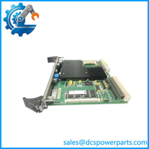
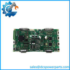
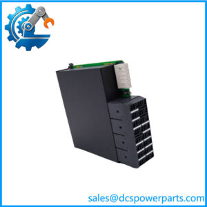
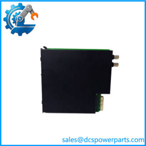
GE Multilin UR6EH | Digital I/O Module | Universal Relay Series
Key Technical Specifications
| Parameter | Specification |
|---|---|
| Manufacturer | GE Multilin |
| Model | UR6EH / UR-6EH |
| Product Type | Digital I/O Module |
| Product Family | Universal Relay Series |
| Digital Inputs | 8 contact inputs |
| Digital Outputs | 4 Form-C outputs |
| Output Contact Type | Form-C / SPDT |
| Relay Platform | GE Multilin Universal Relays |
| Configuration | EnerVista / applicable UR relay configuration |
| Installation | Internal plug-in relay module |
| Weight | Approx. 1.15 kg / 2.55 lb, depending packaging/reference |
| Exact Input Voltage | Verify against relay hardware/configuration |
| Exact Contact Ratings | Verify against applicable UR manual and order code |
| Operating Temperature | Verify against the installed relay configuration |
The 8-input / 4 Form-C output configuration is consistently identified across multiple references. Form-C outputs provide both normally open and normally closed contacts, making the module suitable for status signaling, interlocking, annunciation, and auxiliary control.
Product Introduction
The GE Multilin is a Digital I/O Module for the GE Multilin Universal Relay platform. Its primary purpose is to extend the relay’s discrete interface capability with eight contact inputs and four Form-C outputs, allowing the protection relay to monitor external equipment status and provide relay contacts to associated control circuits. It is a relay-system I/O component, not an independent PLC or standalone remote I/O station.
In a substation or industrial power system, the GE Multilin UR-6EH can be used for breaker and disconnect status, alarm inputs, interlocking signals, permissive logic, trip-related auxiliary signaling, and other discrete control functions handled by the host Universal Relay. The actual logic is implemented by the host relay, including its FlexLogic configuration; the supplies the physical contact interface. GE’s UR platform documentation describes the Universal Relay architecture as modular, with dedicated power supply, CPU, CT/VT, digital I/O, communications, and other hardware modules.
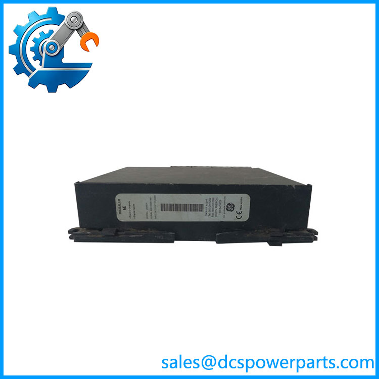
UR6EH
Application Scenarios & Field Pitfalls — The Engineer’s Perspective
Engineering Pain Point
When a UR relay reports a missing contact state or an external control circuit stops responding, the should not automatically be blamed. The fault can be in the field contact, wiring, terminal connection, relay configuration, or the I/O module itself. Because the sits inside the Universal Relay architecture, troubleshooting should start by confirming the expected input/output assignment and then tracing the physical circuit.
Typical Applications
Breaker and disconnect status monitoring
The eight contact inputs can monitor discrete equipment states such as breaker auxiliary contacts, disconnect positions, alarms, and permissive signals.
Substation interlocking
The Form-C outputs can interface the relay’s programmed control logic with external interposing relays, annunciators, or control circuits.
Protection-system auxiliary signaling
The module can provide physical relay contacts for alarms, status indications, and control functions generated by the host UR relay.
Industrial power-system control
Universal Relays are also used in industrial electrical systems, where the same digital I/O architecture can support motor, feeder, transformer, generator, and switchgear applications depending on the host relay model.
Technical Pitfalls
- Do not treat as a standalone I/O module.
It is designed as a hardware module within the GE Multilin Universal Relay architecture. The host relay supplies the processing and logic. - Verify the exact UR relay model.
Universal Relay hardware is modular, but not every module combination is applicable to every relay configuration. Check the relay’s hardware order code before substitution. - Form-C is important.
The four outputs are Form-C/SPDT contacts, providing both normally open and normally closed contact paths. Do not substitute a Form-A-only module simply because the physical module appears similar. - Check the input circuit before replacing the board.
A failed field contact, blown control fuse, incorrect wetting voltage, or open terminal connection can produce the same symptom as a failed digital input. - Check configuration after hardware replacement.
The physical I/O is only one part of the system. Input assignments, FlexLogic equations, output assignments, and protection/control settings remain important. - Do not rely on conflicting reseller specifications.
Some online listings incorrectly add Ethernet communications or describe the as a generic PLC I/O module. The consistent identification is an internal GE Multilin Universal Relay Digital I/O module with 8 contact inputs and 4 Form-C outputs.
Related Products
- GE Multilin UR6CH — Digital I/O module with a different I/O configuration; verify the exact output type before substitution.
- GE Multilin UR6DH — Related Universal Relay digital I/O option.
- GE Multilin UR6FH — Digital I/O option using fast Form-C outputs for applications requiring faster contact operation.
- GE Multilin UR6GH — Related digital I/O module in the UR Series.
- GE Multilin UR6HH — Another UR Series digital I/O configuration.
- GE Multilin UR6LH — Digital I/O option combining Form-A and Form-C outputs with contact inputs.
- GE Multilin UR6NH — Related 4-output/8-input digital I/O configuration.
- GE Multilin UR6PH — Universal Relay digital I/O option.
- GE Multilin UR6RH — Related UR Series digital I/O module.
- GE Multilin UR6TH — Another digital I/O option within the same hardware family.
Procurement Note
For a replacement, provide the complete UR-6EH designation together with the host relay model, relay serial number, hardware order code, and the module label/revision when available. The UR Series contains many visually similar I/O modules with different input/output arrangements, so matching only the physical appearance or the generic “UR digital I/O” description is not sufficient.
For used or surplus inventory, inspect the PCB and connectors for corrosion, contamination, mechanical damage, or previous repair work. Before returning the relay to service, verify every field input and Form-C output against the relay’s configured logic and the original wiring documentation.