Description
Key Technical Specifications
| Parameter | Specification |
|---|---|
| Product Model | SR750-P5-G1-S1-HI-A20-R |
| Manufacturer | GE Multilin / General Electric |
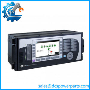
| Product Family | Multilin 750/760 Feeder Management Relay |
| Relay Type | 750 Feeder Management Relay |
| Phase Current Inputs | P5 — 5 A |
| Zero-Sequence Current Input | G1 — 1 A |
| Sensitive Ground Current Input | S1 — 1 A |
| Control Power | HI — 88–300 VDC; 70–265 VAC, 48–62 Hz |
| Analog Outputs | A20 — Eight 4–20 mA outputs |
| Analog Output Accuracy | ±1% of full scale |
| Breaker Status Indicator | R — Red breaker-closed LED |
| Analog Output Isolation | Fully isolated |
| Analog Output Load | Up to 600 Ω for 4–20 mA |
| Output Response | 100% indication in less than 3 power-system cycles |
| Solid-State Trip Rating | 15 A at 250 VDC for 500 ms |
| Trip Output | Form A |
| Close Output | Form A |
| Auxiliary Outputs | Form C |
| Approx. Dimensions | 17.8 × 22.9 × 17.8 cm |
| Approx. Weight | 4.8 kg |
The ordering code itself confirms the major configuration: P5 denotes 5 A phase inputs, G1 denotes 1 A zero-sequence input, S1 denotes 1 A sensitive-ground input, HI specifies the higher control-power range, A20 specifies eight 4–20 mA outputs, and R specifies the red breaker-status LED.
Application Scenarios & Pain Points
A feeder protection retrofit can become surprisingly difficult when the existing CT wiring, control voltage, and analog instrumentation have been in service for years. A relay with the wrong current-input configuration may physically fit the panel and still be electrically wrong.
- Industrial distribution: The 5 A phase-current configuration suits installations using conventional 5 A secondary CT circuits for feeder protection and metering.
- Medium-voltage switchgear: The G1 and S1 inputs provide dedicated 1 A current-input configurations for zero-sequence and sensitive-ground protection schemes.
- Plant DCS interfaces: Eight isolated 4–20 mA analog outputs can provide selected relay measurements to an existing control or monitoring system without requiring a completely new instrumentation architecture.
- Legacy relay replacement: The high-range HI supply option is particularly relevant where the existing panel provides 88–300 VDC or 70–265 VAC control power.
Field note: During replacement work, technicians should verify the actual CT secondary ratings before energizing the relay. A label reading “SR750” is not enough—the P5/G1/S1 configuration matters. Well, technically, even an apparently identical spare can require configuration and firmware verification before it is returned to service.
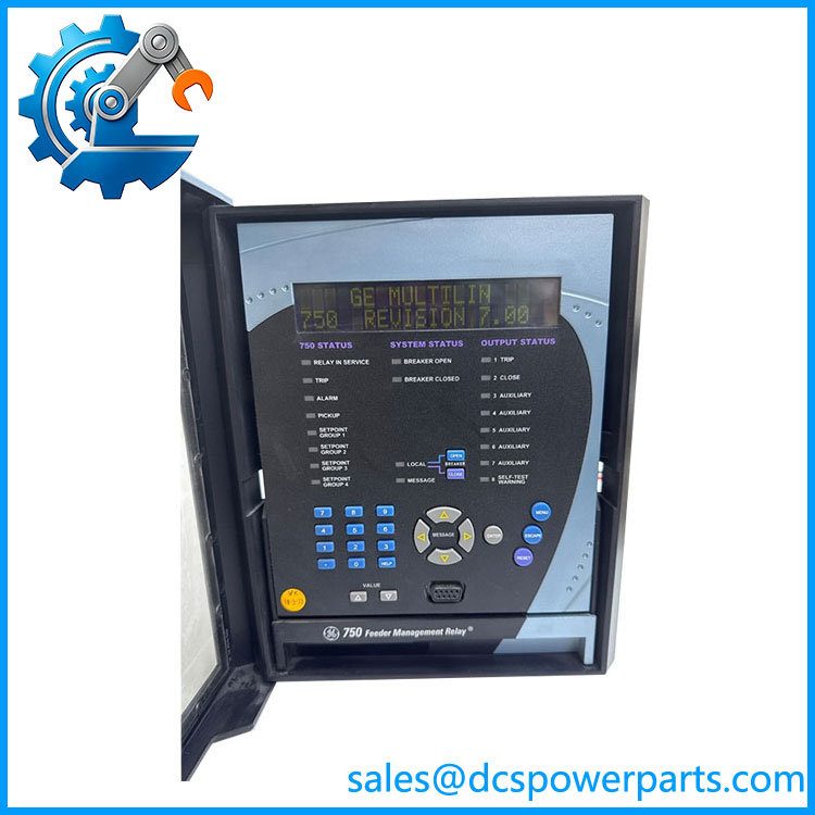
SR750-P5-G1-S1-HI-A20-R
Related Products
- GE Multilin SR750 — The base 750 feeder management relay platform. It provides the same general protection and management architecture, with the exact electrical configuration determined by its ordering code.
- GE Multilin SR760 — A closely related feeder management relay with autoreclose functionality. It is applicable where automatic reclosing is part of the feeder protection scheme rather than simple feeder management.
- GE 750-P5-G5-S5-HI-A20-R — Uses 5 A phase, 5 A zero-sequence, and 5 A sensitive-ground inputs. It may suit installations where the ground-current circuits use 5 A CT secondaries instead of the 1 A inputs of the subject unit.
- GE 750-P5-G1-S1-LO-A20-R — Similar current-input configuration but with the LO control-power option. This is appropriate for lower-voltage control systems rather than the HI supply range.
- GE 750-P1-G1-S1-HI-A20-R — Changes the phase-current input from 5 A to 1 A. This distinction is critical when matching the relay to the installed phase CT secondary.
- GE 750-P5-G1-S1-HI-A20-R-E — Adds the enhanced display option. It is useful when improved local display functionality is required, but it should not be treated as an electrically identical substitute without checking the installed interface requirements.
- GE 750-P5-G1-S1-HI-A20-R-T — Adds the enhanced display with Ethernet 10BaseT option. This is more appropriate for installations requiring the corresponding communication capability.
The Engineer’s Guide: Field Pitfalls to Avoid
⚠️ Do not substitute by the “SR750” name alone.
The order code defines the electrical configuration. Confirm P5, G1, S1, HI, A20, and R against the existing relay before installation. A P1 or G5/G5 configuration can look similar while requiring different CT circuits.
⚠️ Verify control power before energizing.
The HI version accepts 88–300 VDC or 70–265 VAC at 48–62 Hz. Do not assume that every SR750 uses the same control-power range. Check the panel supply and relay label first.
⚠️ Treat firmware and configuration as part of the replacement.
A physically compatible spare can still behave differently if its firmware revision, protection settings, communication configuration, or programmed I/O assignments differ from the existing unit. Save the original settings before removing the old relay whenever possible.
Practical check: Before returning the feeder to service, verify CT polarity, phase-current scaling, zero-sequence wiring, sensitive-ground wiring, trip/close logic, breaker-status indication, and every 4–20 mA output assignment. Also inspect the rear connections for contamination or oxidation—small contact problems can produce much harder-to-diagnose failures later.
Frequently Asked Questions (FAQ)
Can the GE SR750-P5-G1-S1-HI- replace another directly?
Not automatically. The complete ordering code must match the electrical requirements, particularly the P5 5 A phase input, G1 1 A zero-sequence input, S1 1 A sensitive-ground input, HI control power, and A20 analog outputs. The mechanical family alone does not establish interchangeability.
What does P5 mean on -P5-G1-S1-HI-?
P5 identifies 5 A phase-current inputs. This normally corresponds to installations using 5 A secondary phase CT circuits. If the existing relay uses P1, changing to P5 without reviewing the CT arrangement can result in incorrect measurements and protection behavior.
What does A20 mean on the GE ?
A20 specifies eight 4–20 mA analog outputs. The outputs are fully isolated, with a stated accuracy of ±1% of full scale and a maximum listed load of 600 Ω for the 4–20 mA configuration.
Is -P5-G1-S1-HI- supplied with the relay case?
The ordering information and supplier documentation indicate that the 750 relay unit and case can be separate items. Therefore, confirm whether the quoted part is the drawout relay unit only or includes the required mounting/carry case before purchasing.
How should I verify a surplus or refurbished before installation?
At minimum, request confirmation of:
- Exact model/order-code label.
- Hardware revision.
- Firmware revision.
- Protection and control configuration.
- Display/keypad operation.
- Current-input and analog-output testing.
- Condition of rear connectors and terminals.
- Test report and warranty terms.
For a critical feeder, “powers up” is not an adequate acceptance test.
Can this relay be used for a legacy DCS system migration?
Yes, provided the existing protection architecture, CT inputs, control voltage, relay logic, and analog interface requirements match. The eight 4–20 mA outputs can be particularly useful when retaining an existing analog monitoring interface. Communication and protection settings still need to be reviewed as part of the migration rather than assumed from the model number.