Description
Key Technical Specifications
| Parameter | Specification |
|---|---|
| Manufacturer | GE Multilin |
| Model | SR745-W2-P1-G1-HI-E-H |
| Series | 745 Transformer Protection System |
| Protection Configuration | Two windings per phase |
| Phase Current Input | 1 A for all applicable windings |
| Ground Current Input | 1 A |
| Control Power | 90–300 VDC |
| AC Control Power | 70–265 VAC, 48–62 Hz |
| Display | Enhanced 40-character display |
| Front Interface | Expanded keypad and status LEDs |
| Mounting | Standard 19-inch panel mounting |
| Software | EnerVista 745 |
| Communication | Front RS232; rear serial communication options depend on configuration |
| Relay Platform | High-speed, multiprocessor-based transformer protection |
| Typical Application | Power transformer and reactor protection |
The HI suffix is not a generic high-voltage input designation for the transformer itself. It specifically refers to the relay’s high control-power option: 90–300 VDC or 70–265 VAC at 48–62 Hz.
The complete P1/G1 combination also matters during replacement. GE’s ordering table defines P1 as 1 A phase-current inputs and G1 as 1 A ground-current inputs; other 745 variants use 5 A inputs or mixed 1 A/5 A arrangements.
Product Introduction
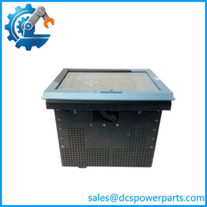
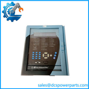
The GE Multilin SR745-W2-P1-G1-HI-E-H is a 745-series transformer protection and management relay configured for a two-winding transformer with 1 A phase and ground current inputs. The 745 platform was designed as a high-speed, multiprocessor-based protection system for small, medium, and large power transformers, combining protection, monitoring, measurement, and control functions in one relay.
This particular configuration includes the enhanced display and keypad arrangement associated with the E-H configuration family. For maintenance work, the complete ordering string is much more useful than the generic “745 relay” description because the CT input ratings and control-power range are encoded directly in the part number.
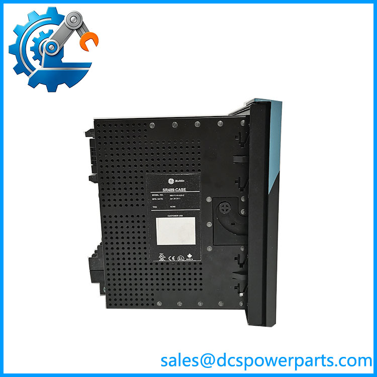
SR745-W2-P1-G1-HI-E-H
Application Scenarios & Field Pitfalls — Engineer’s Perspective
Engineering Pain Point
The biggest replacement risk is ordering a relay from the correct 745 family but with the wrong CT input configuration or control-power option. A relay that physically fits the panel is not necessarily electrically compatible with the existing transformer protection scheme.
Typical Applications
- Two-winding power transformers — differential, overcurrent, ground-fault, thermal, and abnormal-condition protection.
- Industrial substations — transformer protection and monitoring where legacy Multilin 745 equipment remains installed.
- Power-generation facilities — transformer management, measurement, event recording, and protection.
- Transformer refurbishment projects — replacement of aging 745 hardware while preserving the established protection architecture.
Technical Pitfalls to Avoid
- Verify P1 before approving the relay.
P1 means 1 A phase-current inputs. A P5 variant is intended for 5 A inputs, while several other codes combine 1 A and 5 A inputs between windings. Do not substitute based only on “SR745.” - Verify G1 separately from the phase CT rating.
The ground-current designation is independently encoded in the ordering string. G1 corresponds to the 1 A ground-current configuration; G5 is a different hardware option. - Check the control-power supply before energizing.
The HI version accepts 90–300 VDC or 70–265 VAC at 48–62 Hz. Do not apply the low-voltage LO supply assumptions to this unit. - Do not treat the complete ordering code as cosmetic.
The 745 family has numerous combinations for windings, CT ratings, control power, analog options, loss-of-life monitoring, restricted ground fault, communications, and other functions. The exact suffix string should be matched against the relay being removed.
Related Products
- GE Multilin 745-W2-P1-G1-HI — closely related two-winding, 1 A phase/ground configuration without the full suffix shown here.
- GE Multilin 745-W2-P1-G1-HI-T-H — related 745 two-winding configuration with a different option combination.
- GE Multilin 745-W2-P1-G1-LO-E — similar two-winding/1 A configuration using the low control-power range rather than HI.
- GE Multilin 745-W2-P5-G5-HI — two-winding configuration using 5 A phase and ground inputs; not a direct substitute for P1/G1.
- GE Multilin 745-W2-P15-G1-LO-A-R — mixed CT-input configuration with additional options.
- GE Multilin 745-W3 series — three-winding-per-phase versions for transformer applications requiring a third winding input.
- GE Multilin SR469 — transformer/feeder-oriented protection platform with a different application architecture.
- GE Multilin T60 — transformer protection relay from the later UR-family platform; do not treat it as a drop-in 745 replacement without an engineering review.
Procurement Check
For SR745-W2-P1-G1-HI-E-H, verify these items against the existing relay before purchase:
W2 → two windings per phase
P1 → 1 A phase CT inputs
G1 → 1 A ground CT inputs
HI → 90–300 VDC / 70–265 VAC control power
E-H → verify the exact display, hardware, and option configuration from the nameplate and original relay documentation
The 745 ordering code is the safest starting point for replacement approval. Current secondary listings sometimes describe this model with generic voltage, current, IP-rating, and communication specifications that do not match GE’s documented ordering structure; those claims should not override the GE configuration code.