Description
GE Multilin SR489-P5-LO-A1 | Generator Management Relay | 5A CT Low-Voltage Protection
Key Technical Specifications
| Parameter | Specification |
|---|---|
| Product Model | SR489-P5-LO-A1 |
| Manufacturer | GE Multilin |
| Product Family | 489 Generator Management Relay |
| Relay Type | Generator protection and management relay |
| Control Power | 20–60 VDC / 20–48 VAC |
| Frequency | 48–62 Hz for AC control power |
| Phase CT Rating | 5 A secondary |
| Analog Output Configuration | 0–1 mA |
| Analog Inputs | 10 |
| Output Relays | 6 |
| Communication | RS-232 and rear RS-485 interfaces |
| Application | Synchronous and induction generators |
| Front Interface | LED/status and operator interface |
| Mounting | Drawout relay / case |
| Related Case | -CASE |
The closely related 489-P5-LO-A1-E is documented with the same low-voltage supply and 5 A CT configuration, along with 10 analog inputs, six output relays, RS-232, and rear RS-485 interfaces. The A1 configuration is associated with the 0–1 mA analog-output option, while A20 versions use 4–20 mA outputs.
Product Introduction
The is a microprocessor-based 489 Generator Management Relay designed for protection, monitoring, metering, control, and management of synchronous and induction generators. The 489 platform was developed for small- and medium-sized generator applications and integrates electrical measurements with protective functions in a dedicated generator relay.
The is the low-voltage, 5 A CT version with the 0–1 mA analog-output configuration. That option code matters when replacing an installed relay because the otherwise similar P5-LO-A20 configuration uses a different analog-output range. For a brownfield replacement, the complete ordering code should therefore be matched rather than purchasing a generic “489 relay.”
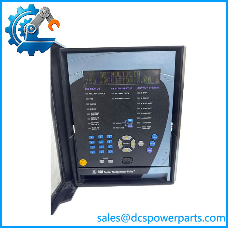
SR489-P5-LO-A1
Application Scenarios & Field Pitfalls — The Engineer’s Perspective
Engineering Pain Point
A generator relay replacement is not simply a matter of matching the enclosure and CT rating. The 489’s ordering code defines important electrical characteristics, including control-power class, CT input rating, and analog-output configuration. A replacement with the wrong option can require rewiring or produce incorrect signals to the plant control system.
For , the most important checks are the low-voltage control supply, 5 A CT inputs, and 0–1 mA analog-output requirement. These should be confirmed against the existing relay nameplate and protection drawings before installation.
Typical Applications
- Industrial Generator Protection: Protection and monitoring of synchronous or induction generators.
- Power Generation Plants: Generator electrical protection and operating-condition monitoring.
- Cogeneration Systems: Generator management within combined heat-and-power installations.
- Process Plants: Protection of plant-owned generation equipment and auxiliary generators.
- Legacy Generator Control Panels: Maintaining existing GE Multilin 489 installations without immediately redesigning the protection system.
Technical Pitfalls to Avoid
- Do not confuse A1 with A20.
The A1 option uses a 0–1 mA analog-output configuration, while A20 versions are associated with 4–20 mA outputs. If the existing PLC/DCS or panel meter expects 0–1 mA, substituting an A20 relay can create a signal-interface problem. - Verify the CT secondary rating.
P5 identifies the 5 A phase-CT configuration. Do not substitute a P1 unit simply because it belongs to the same 489 family; P1 versions use 1 A phase CT inputs. - Check the control-power range.
The low-voltage configuration operates from approximately 20–60 VDC or 20–48 VAC. High-voltage 489 variants have different supply requirements and should not be selected solely from the front-panel appearance. - Confirm the complete case assembly.
The relay is associated with the . GE Multilin 489 documentation specifies mechanical keying between the relay and case, so do not force a relay into a mismatched case. - Power down before withdrawing or inserting the relay.
The 489 installation guidance warns against withdrawing or inserting the relay with control power applied because of the risk of incorrect operation or equipment damage. This is especially important when the relay is installed in an energized generator protection panel. - Review the protection settings before commissioning.
A replacement relay should not be commissioned with factory/default settings. Record the existing generator CT/VT ratios, protection thresholds, trip logic, alarm settings, breaker logic, and communication parameters before removing the original unit. - Treat this as a protection-device replacement, not a routine PLC I/O swap.
CT circuits can carry hazardous energy, and incorrect CT wiring can create serious equipment and personnel risks. Installation and testing should follow the site’s approved electrical-protection procedures.
Related Products
- Low-voltage 489 relay with 5 A CT inputs and 4–20 mA analog-output configuration; compare carefully with the A1 version.
- 489-P5-LO-A1-E: Enhanced-display variant of the low-voltage 5 A / 0–1 mA configuration; verify the complete suffix before substitution.
- 489-P5-LO-A20-E: Low-voltage 5 A CT configuration with 4–20 mA analog output and enhanced-display option.
- 489-P5-HI-A1-E: High-voltage control-power version with 5 A CT inputs and 0–1 mA analog output; not a direct low-voltage replacement.
- 489-P1-LO-A20: Low-voltage version using 1 A phase CT inputs and 4–20 mA analog outputs.
- 489-P1-HI-A20: High-voltage, 1 A CT generator management configuration.
- Matching case assembly for the 489 relay family; verify mechanical keying and installed case configuration.
- 489 Generator Management Relay: The broader 489 platform covering generator protection, monitoring, control, and management.
- EnerVista 489 Setup: Configuration software associated with the 489 relay family and useful for maintaining existing settings and communicating with installed relays.
Procurement Note
For , preserve the complete ordering code when sourcing a replacement. The three most important identifiers are P5 = 5 A phase CT, LO = low-voltage control power, and A1 = 0–1 mA analog-output configuration. The relay is now a legacy/discontinued product, so an available unit should be checked for exact hardware configuration, display/interface version, firmware, and case compatibility rather than accepted solely because it carries the 489 family designation.