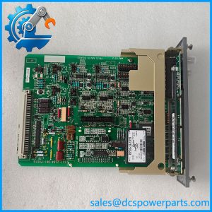
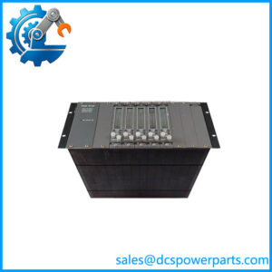
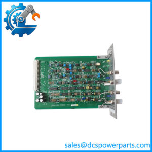
Description
Key Technical Specifications
| Parameter | Specification |
|---|---|
| Manufacturer | Interlogix / GE Security |
| Model | S739DVR-RST1 |
| Product Series | S739 Fiber Optic Transmission |
| Product Type | Optical Video and Data Receiver |
| Transmission Medium | Multimode optical fiber |
| Video Channels | 1 channel |
| Video Direction | One-way reception |
| Control Data | Two-way up-the-coax control |
| Additional Signals | Response and Genlock |
| Video Resolution | Up to 800 TV lines |
| Maximum Transmission Distance | Up to 11 miles (18 km), as specified by the product listing |
| Fiber Configuration | Single multimode fiber |
| Mounting | Rack-mount / standalone |
| Diagnostics | SMARTS diagnostics |
| Video Interface | Verify connector configuration against the original unit |
| Operating Voltage | Verify against the applicable hardware datasheet |
| Power Consumption | Not independently verified |
The model identification and principal transmission specifications are supported by the S739DVR-RST1 product documentation and catalog records.
Product Introduction
GE Interlogix S739DVR-RST1 Fiber Optic Video Receiver
The GE Interlogix S739DVR-RST1 is a rack-mount multimode fiber optic receiver designed for analog video and up-the-coax control data transmission. It receives one video channel over optical fiber while supporting two-way control communication, including response and Genlock signals.
Its primary advantage is combining video and control transmission over one fiber connection. The 800-TV-line resolution specification, transmission distance of up to 18 km, and SMARTS diagnostics make it suitable for geographically distributed surveillance installations.
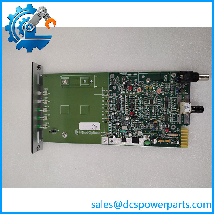
S739DVR-RST1
Application Scenarios & Field Pitfalls
Engineering Pain Point
A remote security camera suddenly loses its video feed at the central monitoring station. The camera itself remains powered, but the control room receives no usable image. Replacing the camera immediately may waste maintenance time because the fault could originate in the optical receiver, fiber connection, or transmitter configuration.
The S739DVR-RST1 provides the receiving end of this transmission path. It is intended for systems that carry video and up-the-coax control information over multimode fiber. Correct transmitter-receiver matching is essential.
Typical Applications
- Power Generation: Remote surveillance of generator halls, substations, and electrical distribution areas.
- Oil & Gas: Video monitoring of remote pipeline facilities, compressor stations, and perimeter security installations.
- Transportation Infrastructure: Centralized camera monitoring across tunnels, transportation facilities, and remote access points.
- Industrial Manufacturing: Optical video transmission between production areas and centralized security control rooms.
Technical Pitfalls to Avoid
1. Receiver and Transmitter Compatibility
The S739DVR-RST1 is a receiver, not a transmitter.
Its corresponding transmission equipment must support the same multimode fiber architecture, video format, and up-the-coax control signaling.
Check the transmitter’s complete model number before ordering. A receiver from the same product family is not automatically compatible with every transmitter variant.
2. Single-Fiber Configuration
This model is specified for one multimode optical fiber.
Do not confuse it with the RST2 version, which is listed as a two-fiber configuration. Check the existing fiber route, optical connectors, and transmitter configuration before replacement.
Also inspect connector cleanliness and optical attenuation. Dirty connectors and damaged fiber can produce intermittent video loss that resembles an electronic module failure.
3. Rack Installation and Signal Verification
The designation identifies the rack-mount configuration.
Before installation, inspect the rack interface, power connections, and module seating. After replacement, verify:
- Video reception and image stability.
- Up-the-coax camera control response.
- Genlock and response signal operation.
- SMARTS diagnostic indications.
- Performance over the actual installed fiber route.
Field recommendation: Do not approve a replacement based solely on the S739 model prefix. Confirm the complete suffix, fiber count, transmission direction, and control-data requirements.
Related Products
The following models belong to the S739 fiber optic transmission family. They provide useful comparison options for receiver replacement, transmitter matching, and fiber-network configuration.
| Model | Product Description | Compatibility and Application |
|---|---|---|
| S739DVT- | Multimode fiber video and data transmitter, rack mount | Transmitting counterpart for compatible S739 receiver installations. Verify exact control-data configuration. |
| -EST1 | Multimode video and up-the-coax data receiver, enclosure mount | Receiver alternative for installations requiring enclosure mounting instead of rack mounting. |
| -EST2 | Multimode video and up-the-coax data receiver, two-fiber configuration | Receiver option for compatible two-fiber transmission arrangements. |
| -RST2 | Multimode video and up-the-coax data receiver, rack mount, two-fiber | Rack-mounted alternative for systems designed around two optical fibers. |
| S739DVT-EST1 | Multimode video and data transmitter, enclosure mount | Transmitter option for enclosure-mounted camera locations. |
| S739DVT-EST2 | Multimode video and data transmitter, two-fiber configuration | Alternative transmitter for compatible two-fiber installations. |
| S739DVT-RST2 | Multimode video and data transmitter, rack mount, two-fiber | Rack-mounted transmitter for matching two-fiber receiver systems. |
| S739DV-PKG | Video and two-way up-the-coax data transmitter/receiver kit | Combined transmission package with two power supplies for compatible installations. |
The model distinctions are documented in the historical UTC Fire & Security product catalog.
Procurement and Replacement Checklist
Before purchasing the GEo, verify:
- Ed.
- Equipment function: Receiver, not transmitter.
- Fiber type: Multimode.
- Fiber count: Single-fiber configuration.
- Video channel requirement: One channel.
- Control requirement: Up-the-coax two-way data.
- Mounting arrangement: Rack-mounted .
- Transmitter compatibility and optical connector type.
- Functional test results for video, control data, and diagnostics.
Final engineerin is a fiber optic surveillance transmission component, not a PLC or DCS I/O module. For industrial security-system maintenance, matching the optical transmission architecture is more important than matching the manufacturer’s name alone.