Description
Product Overview
The GE PCH1026 is a digital structural vibration monitor designed for low-frequency vibration measurement and protection, with particular relevance to wind turbines, tower structures, and industrial mechanical equipment. The unit incorporates three built-in accelerometers, allowing vibration measurement along three axes, while its monitoring architecture can evaluate multiple independent frequencies. Depending on the configured hardware, the PCH1026 can provide one to four independent 4–20 mA outputs, four programmable alarm relays, and one system-fault relay. This makes it suitable for applications where vibration information must be delivered directly to a PLC, DCS, turbine controller, or dedicated protection circuit.
For GE PCH1026, the important distinction is that this is a dedicated vibration-monitoring instrument rather than a conventional PLC I/O module. Its internal accelerometers measure structural movement directly, with configurable measurement values including effective/RMS, maximum, peak, and peak-to-peak levels. The monitor was developed around wind-turbine and structural-monitoring requirements, but the same measurement principle can be applied to machinery foundations and other structures where low-frequency vibration is a concern.
The GE PCH1026 can also form part of a plant protection chain. Programmable alarm relays can provide discrete trip or warning signals, while 4–20 mA outputs can transmit measured vibration values to an existing control system. Communication interfaces vary by configuration and may include RS-232, RS-485, CANopen, Modbus, PROFIBUS, PROFINET, or Ethernet.
To be completely transparent, the exact option configuration matters. A PCH1026 ordered with different communication or output hardware should not be assumed to be electrically interchangeable with another unit simply because both carry the same base model number.
Product Introduction
When tower vibration needs to be monitored independently of the main turbine controller, a dedicated structural monitor can simplify the protection chain. PCH1026 combines three-axis acceleration measurement with up to four independent 4–20 mA outputs and five relay outputs.
For a wind turbine vibration monitoring replacement, the sensor arrangement and relay thresholds should be matched to the existing protection scheme. The unit is also applicable to low-frequency structural monitoring of industrial machinery and building structures.
Key Technical Specifications
| Parameter | Value |
|---|---|
| Manufacturer | GE / PCH Engineering |
| Model | |
| Series | PCH Series |
| Product Type | Digital Structural Vibration Monitor |
| Primary Measurement | Low-frequency structural vibration |
| Integrated Sensors | 3 accelerometers |
| Measurement Axes | X, Y, Z / three-axis configuration |
| Measurement Values | RMS/effective, maximum, peak, peak-to-peak |
| Frequency Monitoring | Up to 4 independent frequencies |
| Analog Outputs | 1–4 × 4–20 mA, configuration-dependent |
| Alarm Relays | 4 programmable independent relays |
| System Fault Relay | 1 |
| Relay Thresholds | Programmable |
| Relay Delay | Programmable |
| Communications | RS-232, RS-485, CANopen, Modbus, PROFIBUS, PROFINET, Ethernet; option-dependent |
| Power Supply | DC |
| Dimensions | Approximately 254 × 130 × 66 mm reported for certain configurations |
| Weight | Approximately 2 kg reported for certain configurations |
| Application | Wind turbines, structural monitoring, rotating machinery |
| Condition | New Surplus — verify exact configuration |
Available technical references identify the as a configurable digital monitor with integrated accelerometers, analog outputs, programmable alarm relays, and optional industrial communication interfaces.
Related Products
- — The primary three-axis structural vibration monitoring platform. Configuration determines the available outputs, relays, and communication interfaces.
- PCH Engineering PCH Series — The broader vibration-monitoring family. Other configurations should be selected according to sensor quantity, measurement range, and application.
- 4–20 mA Vibration Output Configuration — Used when the vibration value must be transmitted directly to PLC/DCS analog input channels.
- RS-485 / Modbus Configuration — Useful where vibration data needs to be integrated digitally into an industrial monitoring network.
- PROFINET Configuration — Relevant where the turbine or machinery control architecture uses PROFINET for controller-level communication.
- PROFIBUS Configuration — Appropriate for legacy automation architectures using PROFIBUS fieldbus infrastructure.
- CANopen Configuration — Relevant to machinery and turbine control architectures based on CANopen.
- Three-Axis Accelerometer Assembly — The integrated sensing arrangement provides X/Y/Z structural vibration measurement and differentiates the monitor from single-axis vibration transmitters.
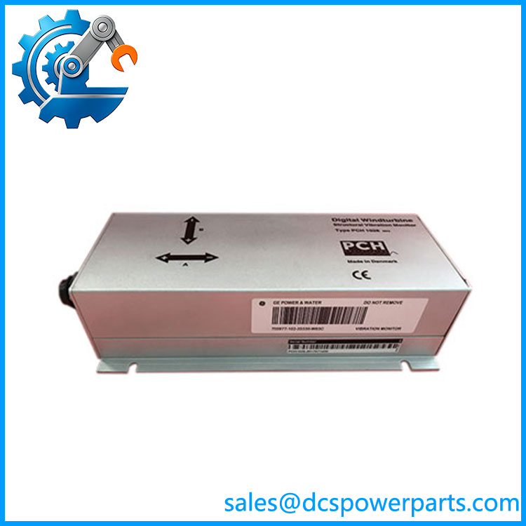
PCH1026
Frequently Asked Questions
What is the GE used for?
The is primarily a low-frequency structural vibration monitor. It has been used in wind-turbine applications for tower vibration monitoring and can also be applied to industrial structures and machinery.
Typical applications include:
- Wind turbine tower monitoring
- Structural vibration monitoring
- Machinery foundation monitoring
- Pumps and compressors
- Fans and generators
- Industrial equipment fault monitoring
Does have built-in accelerometers?
Yes. Available specifications identify three integrated accelerometers, allowing three-axis measurement.
This is significant for structural monitoring because vibration in one direction may not adequately represent the actual movement of the structure.
How many 4–20 mA outputs does have?
The configured unit can provide one to four independent 4–20 mA outputs. The exact number depends on the hardware configuration.
Before ordering a replacement, compare the existing terminal wiring rather than assuming every has four analog outputs installed.
Can connect to a PLC or DCS?
Yes. The monitor can provide analog and relay signals directly to control equipment, while certain configurations support digital communications.
Potential interfaces include:
- 4–20 mA
- RS-232
- RS-485
- Modbus
- CANopen
- PROFIBUS
- PROFINET
- Ethernet
The actual interface must be confirmed from the complete unit configuration.
Can I hot-swap the ?
Do not assume that it can be replaced while energized.
The may form part of a turbine or machinery protection chain where its relay outputs are connected to shutdown or safety functions. Before replacement, identify every relay output, isolate the relevant power and protection circuits, and confirm that the equipment remains in a safe state.
Does provide alarm and fault relays?
Yes. Published specifications identify four independently programmable alarm relays plus one system-fault relay. Alarm thresholds and delay times can be configured.
This permits the monitor to provide both measured vibration information and discrete protection signals.
Will replacing erase my vibration-monitoring settings?
The replacement unit should not be assumed to contain the configuration of the removed monitor.
Before replacement, document:
- Accelerometer configuration.
- Measurement axes.
- Frequency channels.
- Alarm thresholds.
- Alarm delays.
- 4–20 mA scaling.
- Relay assignments.
- Communication parameters.
- Network address.
- Existing firmware/configuration information.
For a turbine application, also preserve the trip thresholds approved for the specific machine.
Does support wind turbine applications?
Yes. The was developed specifically with wind-turbine structural monitoring requirements in mind and is described for tower vibration measurement. A technical reference also describes its use in wind-turbine safety systems for low-frequency vibration monitoring.
How should a New Surplus be tested?
A meaningful acceptance test should verify the sensing system and the protection outputs, not simply confirm that the display powers up.
Recommended sequence:
- Verify the model marking.
- Record serial number and hardware revision.
- Confirm the number and orientation of integrated accelerometers.
- Verify DC supply requirements.
- Check startup diagnostics.
- Apply a controlled vibration input or suitable calibration stimulus.
- Verify X/Y/Z measurement response.
- Check RMS, peak, and peak-to-peak values.
- Verify every installed 4–20 mA output.
- Test all four alarm relay channels where fitted.
- Test the system-fault relay.
- Verify programmed alarm thresholds and delays.
- Test the installed communication interface.
- Confirm data received by the PLC/DCS or turbine controller.
- Record the final configuration and test results.
Procurement note: is configuration-sensitive. For a replacement, the accelerometer arrangement, analog-output count, relay configuration, communications interface, and alarm settings should all be matched before the unit is released for field installation.