Description
Product Overview
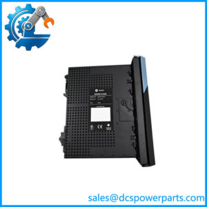
In a high-impedance differential protection scheme, current transformer (CT) saturation during an external fault can create unwanted differential voltage and increase the risk of an incorrect relay operation. The GE Multilin MIB30HICE00000 is identified in product listings as a high-impedance differential protection module associated with GE Multilin protection equipment, including the B30 bus differential relay family. Its role is to support a high-impedance protection circuit through integrated passive components, helping the protection scheme distinguish internal faults from external fault conditions when correctly engineered and commissioned.
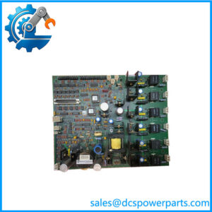
The listed hardware incorporates a 2,000-ohm resistor and a metal-oxide varistor (MOV). The resistor forms part of the high-impedance circuit, while the MOV limits transient overvoltage across the protected circuit. These components are particularly relevant to CT secondary circuits, where external faults can produce substantial transient voltages. The published nominal supply rating is 125 VDC, but the exact role of that supply, the terminal arrangement, and the applicable wiring diagram must be confirmed against the manufacturer’s documentation for the installed protection scheme.
For protection engineers and procurement teams, the GE Multilin MIB30HICE00000 should be selected based on the relay application, CT characteristics, protection-zone design, and required hardware revision—not merely its physical appearance. When replacing an existing module, compare the full model number, terminal markings, mounting arrangement, and associated relay configuration. After installation, qualified protection personnel should verify CT circuit continuity, grounding, resistor and MOV integrity, and the prescribed differential protection settings and trip logic. A matching part number is an important first check, but it does not establish that the complete protection scheme is correctly configured or ready for service.
Product Introduction (Non-Templated)
External faults can place substantial transient stress on CT secondary circuits, making the correct high-impedance protection components important to a substation’s protection design. The GE Multilin MIB30HICE00000 is listed as a high-impedance differential module associated with the B30 bus differential protection family.
Its published specifications include a 2,000-ohm resistor and 125 VDC nominal supply. For a bus protection upgrade or legacy replacement, confirm the approved circuit design, terminal connections, and relay compatibility before commissioning.
Key Technical Specifications
| Parameter | Value |
|---|---|
| Product Model | MIB30HICE00000 |
| Alternate Designation | MIB-3-0-HI-C-E-000-00, as listed by a supplier |
| Manufacturer / Brand | GE Multilin; associated with GE Vernova |
| Product Type | High-Impedance Differential Protection Module |
| Protection Application | High-impedance differential protection |
| Associated Relay Family | GE Multilin B30 bus differential protection |
| Nominal Operating Voltage | 125 VDC, reported |
| Integrated Resistance | 2,000 ohms, reported |
| Overvoltage Suppression | Integrated metal-oxide varistor (MOV), reported |
| Dimensions | 248 × 136 × 52 mm, reported |
| Net Weight | 1.12 kg, reported |
| Mounting Method | Plug-in installation on a designated protection panel or rack; confirm exact assembly |
| Protection Rating | IP20, reported |
| Operating Temperature | −10°C to +60°C, reported by one supplier |
| Relative Humidity | 5–85%, non-condensing, reported |
| Communication Protocol | No independent communication protocol verified |
| Condition | New surplus; confirm packaging and test status |
Specification caution: The values above are supplier-published details, not a substitute for the manufacturer’s official technical manual. Confirm the exact voltage rating, environmental limits, mechanical dimensions, and circuit requirements before using them as engineering acceptance criteria.
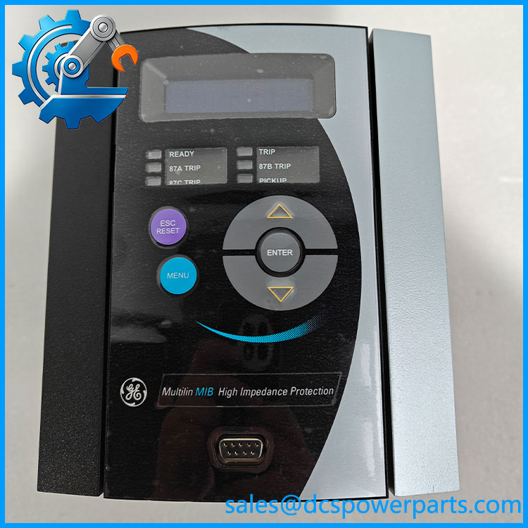
MIB30HICE00000
Related Products
The following products and components are relevant to differential protection applications. Their inclusion does not imply direct interchangeability with the MIB30HICE00000.
- GE Multilin B30 — Bus differential protection relay family associated with the MIB30HICE00000 in supplier documentation. Confirm the specific relay model and approved module configuration before replacement.
- GE Multilin HID32 — Listed as a related high-impedance differential protection module. Verify its electrical characteristics and application before considering it as an alternative.
- GE Multilin SR735 — A feeder protection relay listed in related product information. It serves a different protection application and is not a direct substitute for a high-impedance differential module.
- GE Multilin B90 — A bus differential protection relay family worth evaluating when reviewing broader bus protection architectures. Confirm the required protection design and hardware compatibility independently.
- Current Transformer (CT) Assembly — Supplies the secondary currents used by the differential protection scheme. CT ratio, polarity, accuracy class, and saturation characteristics must match the protection design.
- High-Impedance Stabilizing Resistor — Establishes the required circuit resistance in high-impedance differential schemes. The required resistance and power rating must be calculated for the specific application; do not substitute a generic resistor for the integrated assembly.
- Metal-Oxide Varistor (MOV) Assembly — Limits transient overvoltage in the protection circuit. Its voltage rating, energy capability, and coordination with the CT circuit must match the approved design.
- Differential Protection Test Equipment — Used by qualified protection personnel to verify pickup behavior, stability, and trip logic during commissioning or maintenance.
Frequently Asked Questions (FAQ)
1. What is the GE Multilin used for?
The is listed as a high-impedance differential protection module associated with GE Multilin protection systems, including the B30 bus differential relay family.
Its integrated resistance and MOV support the electrical behavior and transient protection requirements of a properly designed high-impedance differential circuit. The complete protection function depends on the CT arrangement, relay settings, circuit wiring, and approved application design.
2. Is the compatible with the GE Multilin B30 relay?
Supplier listings associate this module with the B30 bus differential protection family. However, compatibility should be confirmed for the exact relay hardware and protection configuration.
Before ordering, check the relay model, installed module designation, wiring diagram, terminal assignments, and applicable revision documentation. Do not assume that every B30 configuration uses the same module.
3. Does the support firmware version 3.1?
A verified firmware compatibility matrix for this exact module was not available. Firmware version 3.1 therefore cannot be confirmed as compatible.
Check the relay’s hardware and firmware documentation to determine whether the module is passive protection circuitry or has revision-specific electronic requirements. Confirm the complete protection system configuration before commissioning.
4. Can I hot-swap the while the protection relay is operating?
Do not assume that live replacement is permitted. Removing a component from an active differential protection circuit may compromise the protection zone or interrupt a critical circuit.
Use the site’s approved switching and maintenance procedure. Determine whether the protected equipment must be placed under alternative protection before work begins, and verify the isolation and restoration steps with qualified protection personnel.
5. How can I verify that a new-surplus is genuine?
New-surplus condition alone does not establish authenticity or functional performance. Request:
- Clear photographs of the complete model number and physical markings.
- Available traceability records and original packaging details.
- Inspection results for terminals, mounting points, corrosion, and component damage.
- Test documentation identifying the resistance, MOV condition, and any other checks actually performed.
For a protection-critical application, distinguish component-level inspection from a complete relay and differential circuit commissioning test.
6. Will replacing the erase the relay settings or protection logic?
Replacing a passive component assembly would not ordinarily erase settings stored in a separate protection relay. However, this should not be assumed without confirming the exact hardware design.
Before replacement, preserve the relay settings and approved protection study, document the existing wiring, and follow the manufacturer’s replacement procedure. Afterward, perform the required secondary-injection or other approved protection tests before returning the system to service.
7. What warranty and testing should I request when buying the ?
Confirm the warranty period, coverage, return conditions, and exclusions in writing. Ask the supplier to identify the unit’s actual condition rather than relying solely on a new-surplus label.
For a high-impedance differential module, request documented checks of the integrated resistance, MOV condition, terminal integrity, and physical assembly. Confirm whether functional testing was performed and which parts of the complete protection scheme remain to be tested on-site. A component inspection alone does not prove that the installed bus differential protection will operate correctly.