Description
GE IS200TRPGH1BDE Primary Trip Terminal Board
Product Introduction
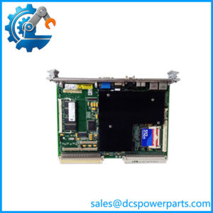
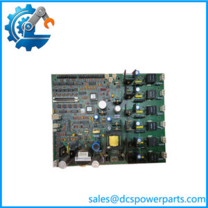
The GE IS200TRPGH1BDE is the full ordering identifier for a GE Mark VI TRPG Primary Trip Terminal Board used in turbine protection systems. The underlying IS200TRPGH1B board provides the hardwired relay interface between turbine protection logic and the electrical trip devices (ETDs) that initiate turbine shutdown. In the documented TMR configuration, the board contains nine magnetic relays arranged as three voting circuits, with three relays associated with each of three trip solenoids. This arrangement implements hardware 2-out-of-3 voting at the trip interface rather than relying solely on software logic.
The GE IS200TRPGH1BDE also interfaces with up to eight Geiger-Mueller flame detectors in the applicable gas-turbine configuration. The TRPG works with the TREG Emergency Trip Terminal Board to provide the primary and emergency sides of the ETD interface. In Mark VI systems, the VTUR board interfaces with TRPG through the VME-based control architecture. In Mark VIe systems, PTUR I/O packs on the TTURH1C terminal-board assembly can control the TRPG interface.
For the GE IS200TRPGH1BDE, the final two-letter suffix should not be casually discarded when purchasing a replacement. Available procurement records associate IS200TRPGH1BDE with the IS200TRPGH1B board family, but the exact ordering identifier should still be matched against the installed board and cabinet documentation. This is a turbine protection component, so relay configuration, terminal wiring, TREG relationship, and controller/interface revision all matter more than a superficial physical match.
Technical Specifications
| Parameter | Specification |
|---|---|
| Product Model | IS200TRPGH1BDE |
| Base Board | IS200TRPGH1B |
| Manufacturer | General Electric |
| Functional Acronym | TRPG |
| Product Type | Primary Trip Terminal Board |
| System | GE Mark VI / Mark VIe |
| Primary Application | Gas turbine protection and trip control |
| Trip Solenoids | 3 |
| Magnetic Relays | 9 |
| Voting Architecture | Hardware 2-out-of-3 voting |
| TMR Support | Yes |
| Trip Solenoid Supply | 125 VDC |
| Control Relay Coil Supply | 28 VDC |
| Flame Detector Inputs | 8 Geiger-Mueller detectors |
| Flame Detector Supply | 335 VDC is reported for the documented flame-detector circuit; verify against the applicable system drawing |
| Current Suppression | Metal-oxide varistors (MOVs) |
| Associated Board | TREG Emergency Trip Terminal Board |
| Mark VI Controller Interface | VTUR |
| Mark VIe Controller Interface | PTUR packs / TTURH1C |
| Field Interface | Trip-solenoid and flame-detector terminal wiring |
| Diagnostics | Relay-driver feedback, contact status, solenoid power bus, flame-detector excitation monitoring |
| Board Identification | ID devices on connector interfaces |
| Primary Protection Logic | Hardware relay/voting interface |
| Manual Reference | GEH-6421J |
The 125 VDC trip-solenoid supply, 28 V control-relay supply, three trip solenoids, nine relays, and eight flame-detector inputs are reported consistently in technical records for the IS200TRPGH1B family.
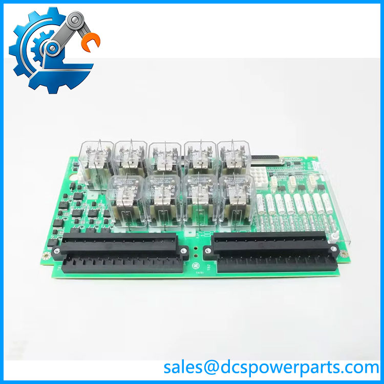
IS200TRPGH1BDE
Main Features and Engineering Considerations
1. Hardware-Based TMR Voting
The defining feature of the H1B configuration is its three-channel relay architecture. Nine magnetic relays are arranged across three trip-solenoid circuits. In a TMR system, the relay arrangement provides hardware 2-out-of-3 voting. This gives the trip interface a physical voting layer independent of ordinary software sequencing.
2. Three Primary Trip Solenoids
The TRPG board interfaces three trip solenoids or electrical trip devices. The main protection relays on TRPG are controlled by the upstream I/O/protection electronics and provide the final relay interface to the trip circuit. The three-channel arrangement is central to the TMR implementation.
3. Relationship with TREG
TRPG should not be considered in isolation. The TRPG and TREG boards form the primary and emergency sides of the ETD interface. The TREG side is associated with the emergency overspeed protection architecture, while TRPG handles the primary protection interface.
4. Flame Detector Interface
The gas-turbine configuration can accept inputs from eight Geiger-Mueller flame detectors. The flame-detector connections are made directly to the applicable terminal block, with excitation power supplied through the board’s associated connections.
5. Relay Diagnostics
The associated I/O electronics monitor relay-driver feedback and contact status. The documented diagnostics also monitor the solenoid power bus and flame-detector excitation voltage. This means a TRPG-related alarm does not necessarily mean that a relay itself has failed; wiring, supply voltage, connector identification, or the downstream trip circuit can also be involved.
6. Board Identification
TRPG includes identification devices associated with its connectors. The I/O electronics can query board type, serial number, revision, and connector location. A mismatch can therefore produce a hardware-compatibility fault even when the replacement board appears physically identical.
7. Mark VI and Mark VIe Integration
The TRPG family can be used in both Mark VI and Mark VIe-related architectures. Mark VI installations use the VTUR interface, while Mark VIe arrangements use PTUR packs associated with TTURH1C. This does not mean every TRPG revision is interchangeable between systems; the complete architecture must be verified.
Application Scenarios
- GE gas turbine emergency-trip systems
- Mark VI turbine protection
- Mark VIe turbine protection architectures
- TMR turbine shutdown systems
- Primary turbine trip circuits
- Electrical Trip Device (ETD) interfaces
- Trip-solenoid control
- Overspeed protection interface
- Combustion flame detection
- GE Speedtronic turbine control cabinets
- Legacy turbine protection-system maintenance
Engineer’s Guide: Field Pitfalls
Do not confuse TRPG with TREG.
TRPG is the primary trip terminal board. TREG provides the associated emergency-trip side of the ETD interface. The two boards work together but have different functions.
Do not substitute H2 hardware merely because the board looks similar.
H1A/H1B configurations use three voting relays per trip solenoid for TMR systems. H2A/H2B versions use one relay per trip solenoid for simplex applications. The architecture is materially different.
Verify the 125 VDC trip circuit.
The trip-solenoid power is a critical field circuit. Confirm the installed voltage, polarity, protection, and downstream solenoid characteristics before commissioning.
Check relay feedback, not just relay energization.
The Mark VI diagnostics can monitor relay-driver and contact feedback. A mismatch can result from a contact problem, wiring issue, supply fault, or downstream ETD condition rather than a failed PCB.
Verify flame-detector wiring separately.
The eight flame-detector inputs are part of the protection interface. Their excitation circuit and terminal assignments should be checked independently from the trip-solenoid wiring.
Do not assume the suffix is cosmetic.
For , retain the complete ordering identifier in procurement records. Compare the board label, connector arrangement, revision, and cabinet drawings before approving a replacement.
Check the TMR voting chain after replacement.
Because this board participates directly in the trip path, functional testing should verify each channel and the intended 2-out-of-3 behavior under the site’s approved turbine protection test procedure.
Use controlled maintenance procedures.
The board can interface with 125 VDC trip circuits and, in applicable configurations, much higher flame-detector excitation voltages. It should not be treated as an ordinary low-voltage PLC terminal board.
Frequently Asked Questions
What is GE ?
It is the full ordering identifier associated with the GE IS200TRPGH1B TRPG Primary Trip Terminal Board, used in Mark VI turbine protection systems.
What does TRPG stand for?
TRPG refers to the Primary Trip terminal-board function within the GE Mark VI turbine protection architecture.
How many trip solenoids does the TRPG support?
The documented TRPG architecture supports three trip solenoids / electrical trip devices.
How many relays are on the H1B version?
The H1B configuration has nine magnetic relays, arranged as three voting circuits.
Does support TMR?
Yes. The H1A/H1B configurations are designed for TMR applications, with three voting relays associated with each trip solenoid and hardware 2-out-of-3 voting.
What is the trip-solenoid voltage?
Technical records identify 125 VDC for the trip-solenoid supply. The actual installed circuit should always be verified against the turbine’s electrical drawings before maintenance.
Does TRPG handle flame detection?
Yes. The documented gas-turbine configuration accepts inputs from eight Geiger-Mueller flame detectors.
Which board works with TRPG for emergency protection?
The TREG Emergency Trip Terminal Board works with TRPG to form the primary and emergency sides of the electrical trip-device interface.
What should be checked before purchasing?
Verify the complete identifier, H1B/TMR configuration, board revision, VTUR or PTUR interface, TREG board, trip-solenoid voltage, flame-detector configuration, terminal wiring, and relay diagnostic arrangement.
Procurement Note
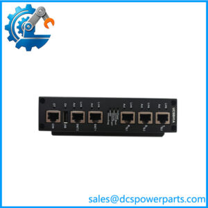
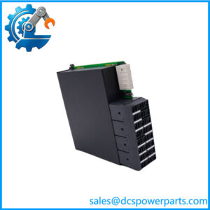
For a replacement , I would require a clear photograph of the complete board label and terminal/connector side. The critical checks are:
- Full part-number and revision matching.
- H1B/TMR architecture confirmation.
- Three-solenoid configuration.
- Nine-relay configuration.
- TREG compatibility.
- VTUR or PTUR/TTUR interface confirmation.
- 125 VDC trip-circuit verification.
- Flame-detector wiring and excitation verification.
- Relay-contact and driver-feedback testing.
For refurbished inventory, a supplier’s statement that the board “powers on” is not meaningful functional evidence by itself. The relevant test is whether the relay-driver circuits, contact feedback, terminal paths, and identification circuitry behave correctly within the applicable Mark VI protection configuration.