Description
Product Overview
IS200TRPGH1BDD is the board where a turbine’s primary trip circuit becomes physical. Its functional name is exact: the primary trip termination board. Everything upstream of it is logic — the protection processor, the overspeed algorithms, the voting — and everything downstream is the three trip solenoids that actually latch the turbine’s stop valves closed. The board sits between those two worlds, and its job is to terminate the solenoids, supply and terminate the flame detectors, and suppress the inductive kick that a 125 V DC solenoid generates when its current is interrupted.
The device count says most of what an engineer needs. Three trip solenoids at 125 V DC, one per protection channel, which is the field-side expression of a voted trip architecture: three independent channels, three solenoids, and the machine trips when the voting logic agrees. Alongside them, up to eight flame detectors supplied at 335 V DC — the high voltage a self-checking ultraviolet scanner needs — with their circuits terminated on the same board. A 28 V control relay coil interface sits in the same assembly. The field wiring lands on two large terminal blocks of 24 terminals each, numbered 1 to 48, which is the detail that makes the board maintainable: a numbered termination map rather than a bundle of wires identified by tags.
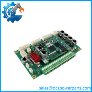
The physical construction is consistent with that role. On the H1A base of this design, the board carries nine transformers in two rows of four and five, eight yellow capacitors, sixteen small white capacitors in eight pairs, and the two black terminal blocks — a power and interface section rather than a logic section. That is the signature of a termination board: isolation and supply components, suppression components, and terminals, with the intelligence living elsewhere in the rack.
The suppression choice is where this board influences timing rather than merely passing current. A 125 V DC trip solenoid has an L/R time constant of about 0.1 s given on the specification, and the metal oxide varistor across it determines how that stored energy is dissipated when the circuit opens. A varistor clamps the inductive spike and therefore also shapes the current decay, which means the solenoid’s drop-out time is a function of the board’s suppression — not only of the solenoid. Replacing a varistor with a different part, or removing one because it “keeps blowing”, changes the trip timing of the very circuit the board exists to protect.
The trip circuit itself is usually built as a pair of boards rather than one. The primary trip termination board provides one leg of the 125 V DC trip supply and terminates the solenoids, while its partner board supplies the other leg and carries the relay channels that the protection processor drives; the protection processor — the VPRO board — commands the trip, and the three-solenoid arrangement completes a 2-out-of-3 voted trip function in the field. That is why these boards are sold as a cluster, and why a buyer should know which leg and which function the board in hand represents before assuming a sibling part will substitute.
Two further attributes matter at ordering. First, the H1 group and the H2 group are not the same board with a different label: the H2B build is quoted at the same three 125 V DC solenoids and eight flame detectors but adds twelve output relay channels, so the group field changes the channel complement. Second, the trailing two letters — DD here, and DE, BDE in circulation — are the build field, and the H1A base is documented as conformally coated, the coating that lets a board survive the sulphur, salt and humidity of a turbine hall. A board that seats but carries the wrong build field is the failure mode this part number punishes.
Technical Specifications
| Parameter | Value |
|---|---|
| Model | IS200TRPGH1BDD — base IS200TRPGH1B, build suffix DD |
| Manufacturer | GE (General Electric), GE Industrial Systems — made in USA |
| Product type | Primary trip termination board (TRPG) |
| Platform | Mark VI / Mark VIe protection assembly; IS200 terminal board designation |
| Trip solenoids | 3, rated 125 V DC |
| Solenoid circuit | L/R time constant 0.1 s; metal oxide varistor (MOV) suppression |
| Control relay coil | 28 V |
| Flame detector supply | 335 V DC, up to 8 flame detectors |
| Field terminals | Two blocks, 24 terminals each, numbered 1–48 |
| Construction (H1A base) | 9 transformers in two rows (4 + 5), 8 yellow capacitors, 16 small capacitors in 8 pairs, two black terminal blocks |
| PCB coating | Conformal coating (documented on the H1A base of this design) |
| Functional revision | H1B base; build field DD |
| Group distinction | H2 group build (e.g. IS200TRPGH2B) adds 12 output relay channels on top of the same solenoid and flame-detector complement |
| Circuit role | Field termination of the primary trip solenoids and flame detection circuits; typically paired with a partner termination board supplying the other trip leg |
| Related logic element | VPRO protection processor, which commands the trip through its relay channels |
| Assembly codes | Printed assembly codes appear on this family (e.g. S1C5029 on an IS200TRPGH1BDD unit) — board identity, not a catalog number |
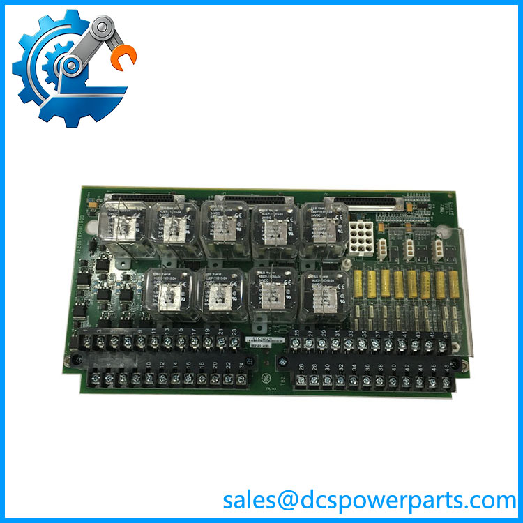
IS200TRPGH1BDD
Key Features and Advantages
Three solenoids, three channels: the board terminates one 125 V DC trip solenoid per protection channel, matching the voted architecture instead of collapsing it at the terminals.
Suppression engineered for a 125 V DC inductive load: MOV clamping on a circuit with a 0.1 s L/R constant, so the trip solenoid’s stored energy is dissipated at the board rather than in the wiring or across a relay contact.
Flame detection on the same board: 335 V DC supply and termination for up to eight detectors, which keeps the combustion monitoring circuits in one documented place instead of scattered across the cabinet.
48 numbered terminals: two blocks of 24, numbered 1 to 48, so the termination map is printed rather than remembered — the difference between a 30-minute check and an afternoon of tracing.
Conformal coating: the chemical barrier that keeps a board alive in a turbine hall’s sulphur and humidity, documented on this design’s base revision.
Passive by design: no processor and no firmware, so a board failure is diagnosed with a meter and the wiring schedule rather than a download — and a replacement needs no configuration.
A group field that means something: H1 and H2 builds differ in channel complement, with the H2 build adding twelve relay channels, so the group letter is a specification rather than decoration.
Documented field pairing: the board’s role is defined against its partner termination board and the VPRO processor, which is the information a spare needs before it is ordered rather than after it fails.
Applications
Gas turbine primary trip circuits: the three trip solenoids that latch the fuel and stop valves, terminated at 125 V DC with suppression at the board.
Steam turbine emergency shutdown: the same primary trip architecture on steam machines, where the trip solenoids act on the main stop valve and the intercept valves.
Combustion monitoring: up to eight flame detectors supplied at 335 V DC, with their circuits terminated alongside the trip circuits so a flame loss and a trip are serviced from one board.
TMR-protected turbine cabinets: installations where three independent protection channels each own a solenoid, and the field termination must not introduce a common point that defeats the voting.
Protection assembly refurbishment: cabinets being restored around a VPRO processor and its termination boards, where the original field wiring must be preserved and only the board replaced.
Spares holding for Mark VI / Mark VIe turbine panels: the board is a wear-and-suppression item, and the exact build field is what makes a spare usable.
Not a substitute for the H2 group build where twelve output relay channels are required, and not the board that supplies the opposite leg of the trip circuit — those are different parts in the same assembly.
Related Products
IS200TRPGH1A — the earlier base of the same design, group 1, revision A, conformally coated; the H1A reference for construction and terminal layout. IS200TRPGH1B — the base model of this unit; group 1, revision B, with the 3 × 125 V DC solenoid and 8 × flame detector complement. IS200TRPGH1BDE / IS200TRPGH1BDD — adjacent build fields of the same base; the two-letter tail is the field to match. IS200TRPGH2B — group 2 build: same three solenoids and eight flame detectors plus twelve output relay channels. IS200TREGH1BEC — partner termination board of the protection assembly, carrying the relay channels the VPRO drives; the other leg of the trip circuit. IS200TREGH2BDC — the group 2 partner board, quoted with twelve relays of which nine are used in the trip configuration. IS200VPROH1B — the protection / overspeed processor that commands the trip; the logic element this board serves. IS200TCTG — turbine trip board elsewhere in the Mark VI trip architecture, a different function despite the shared subject.
Installation and Maintenance
Before installation: confirm the build field on the board matches the record — DD here, with DE and other tails in circulation — and confirm which leg of the trip circuit this board represents, since the primary trip termination board is one half of a pair. Verify the installed trip solenoids are the 125 V DC type the board is built for, and that the flame detectors are the type expecting a 335 V DC supply. Check the replacement’s terminal numbering against the cabinet’s wiring schedule before anything is disconnected.
Installation: land field wiring on the two 24-terminal blocks following the 1–48 numbering rather than by position memory, and record the mapping as it is removed. Do not remove or substitute the metal oxide varistors: they set both the clamping level and the current decay on a 0.1 s L/R solenoid circuit, so a different varistor changes the trip timing of the channel. Treat the 335 V DC flame detector supply as hazardous — isolate and allow it to discharge before touching those terminals. Keep the conformal coating intact; a scratched coating over a high-impedance node is how a board fails a year later in a humid hall.
Maintenance: verify solenoid drop-out behaviour after any change to a solenoid, a varistor or the field wiring, because the timing is a property of the circuit rather than of the board alone. Inspect the varistors for discoloration or leakage and the terminal blocks for heat marks, which indicate a solenoid drawing more than its rated current. Check the three channels are matched — one lazy solenoid among three is a voting problem disguised as a mechanical one. Hold spares at the exact base and build field, note the printed assembly code from the board alongside the catalog number, and if a group 2 build is what the cabinet needs, do not accept a group 1 board because the terminals look the same.
Warranty and Quality
Every IS200TRPGH1BDD unit is supplied as the primary trip termination board, base model IS200TRPGH1B with the DD build field, and is described with the device complement that defines it: three 125 V DC trip solenoids with MOV suppression and a 0.1 s L/R time constant, a 28 V control relay coil interface, a 335 V DC supply for up to eight flame detectors, and two terminal blocks of 24 terminals numbered 1–48. Units are inspected for terminal-block condition and thread integrity, varistor condition and absence of prior substitution, transformer and capacitor condition on the board surface, conformal coating integrity, board-edge and mounting wear, silkscreen legibility, printed assembly code, and for evidence of prior repair or rework. Technical description is drawn from the documentation circulated for this family — the H1A base’s conformal coating, transformer and capacitor arrangement and 48-terminal layout; the H1B build’s solenoid, flame detector, suppression and supply figures; the H2B build’s additional twelve relay channels; and the assembly pattern in which the primary trip termination board is paired with the protection processor’s relay termination board to complete a voted trip circuit. Where sources differ on whether this board belongs to Mark VI or Mark VIe, both are recorded: the IS200 designation is the board-level identity, and the VPRO / TREG pairing is the architecture that decides compatibility. A 12-month repair, replacement or refund commitment applies. Technical support covers what this part actually requires: matching the build field, distinguishing the H1 and H2 groups and the two legs of the trip circuit, keeping varistor suppression as designed so that trip timing is preserved, and reading the assembly code off the board when the catalog number and the cabinet record disagree.