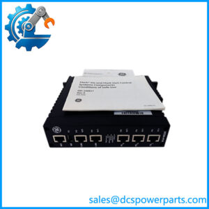
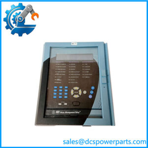
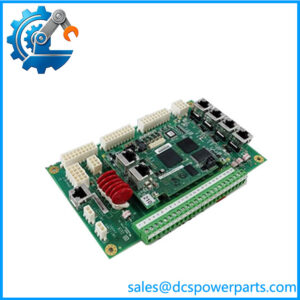
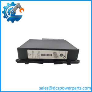
Description
GE IS200TRLYH1BGF | Termination Relay Board | Mark VI Relay Output Interface
Key Technical Specifications
| Parameter | Specification |
|---|---|
| Manufacturer | GE General Electric |
| Part Number | IS200TRLYH1BGF |
| Functional Family | TRLY |
| System | GE Mark VI Speedtronic |
| Board Type | Termination Relay Board |
| Base Model | IS200TRLYH1B |
| Relay Quantity | 12 plug-in relay circuits |
| Field Terminals | 48 |
| Relay Type | Plug-in mechanical relays |
| Relay Feedback | Coil sensing / voted coil-drive feedback |
| Suppression | MOV-based suppression documented on H1B family |
| I/O Architecture | Simplex and TMR |
| Compatible I/O Pack Family | PDOA / YDOA |
| Mounting | Mark VI terminal-board architecture |
| Application | Turbine control and relay output interface |
The IS200TRLYH1B family uses 12 plug-in magnetic relays. The first six relay circuits can be configured for external solenoid drive or dry Form-C contact operation, while other relay circuits provide isolated Form-C contacts for specialized applications.
Published relay data for the family includes a 3.0 A relay rating, 500 VAC contact-to-contact dielectric rating, and 1,500 VAC coil-to-contact dielectric rating. Typical relay operating time is reported at approximately 10 ms. These values should still be checked against the exact board documentation and installed relay configuration before applying them to a protection circuit.
Product Introduction
The GE IS200TRLYH1BGF is a TRLY termination relay board from the GE Mark VI turbine control platform. Its job is to take output commands from the Mark VI I/O architecture and provide relay contacts or energized field outputs for devices such as solenoids, valves, and other turbine-control circuits.
The underlying H1B design supports both simplex and TMR configurations through the appropriate PDOA/YDOA I/O pack arrangement. In TMR installations, the board uses the JR1, JS1, and JT1 connections; simplex operation uses JA1.
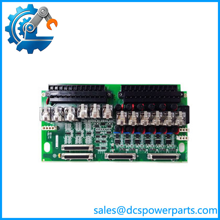
IS200TRLYH1BGF
Application Scenarios & Field Pitfalls — Engineer’s Perspective
Engineering Pain Point
A TRLY board is not simply a collection of replacement relays. The relay wiring, jumper configuration, suppression arrangement, I/O-pack interface, and Mark VI architecture all affect whether a replacement board can be commissioned correctly.
Typical Applications
- Turbine valve and solenoid control — Relay outputs can interface with field solenoids and related actuators.
- Turbine trip circuits — Relay contacts can participate in shutdown or protective-control logic where the project design specifies the TRLY board.
- General Mark VI relay outputs — Provides discrete relay interfaces between controller outputs and field wiring.
- TMR turbine control — Supports redundant I/O connections through the documented JR1/JS1/JT1 architecture.
Technical Pitfalls to Avoid
- Do not treat
IS200TRLYH1BGFas a generic PLC relay module.
It belongs to the Mark VI terminal-board architecture and must be evaluated together with the associated I/O pack and system wiring. - Do not substitute another TRLY suffix solely because the base number matches.
Current technical listings explicitly distinguish multiple TRLYH1B suffix configurations. Revision compatibility should be confirmed from the GE project documentation, board nameplate, and I/O-pack arrangement. - Check the jumper and fuse configuration before removal.
The H1B design uses selectable relay circuits and field power arrangements. A replacement board should reproduce the required configuration rather than being installed with factory/default settings. - Verify simplex versus TMR wiring.
The connector arrangement changes according to architecture. Using the wrong connection scheme can prevent proper output control or redundancy operation. - Do not confuse TRLY with a controller or I/O processor.
The TRLY is the field relay interface. The associated I/O pack performs the controller-side interface and diagnostics. - Check the actual field load before energizing.
Relay contact ratings alone do not establish suitability for every solenoid or valve. Coil current, inrush, suppression, voltage, and the selected board configuration must all be considered.
Related Products
- IS200TRLYH1B — Base TRLY relay terminal-board family. The documented H1B architecture provides the reference point for the
H1BGFconfiguration. - IS200TRLYH1C — Later TRLY relay-output terminal-board variant; configuration and suppression details differ, so it should not be assumed interchangeable.
- IS200TRLYH1BDC — TRLY relay-output/coil-sensing variant with a different full suffix.
- IS200TRLYH1BEC — Relay-output terminal-board variant within the TRLY family.
- IS200TRLYH1D — Mark VI relay-output terminal-board variant.
- IS200TRLYH1F — Another TRLY relay-output board configuration.
- IS200TRLYH1FAA — Configured TRLY terminal relay-output board.
- IS200TRESH1A — Mark VI Trip Emergency Board; a different protection function from the TRLY relay interface.
- PDOA I/O Pack — Associated I/O-pack family documented for TRLYH1B simplex/TMR applications.
- YDOA I/O Pack — Alternative documented I/O-pack family for TRLYH1B applications.
Procurement Note
For IS200TRLYH1BGF, verify the following before accepting a replacement:
complete part number → H1BGF suffix → board revision → relay configuration → jumper positions → field voltage → I/O pack → simplex/TMR architecture → terminal wiring.
One important distinction: some current listings describe this part as a generic “Mark VIe relay output module.” The stronger identification is a GE Mark VI TRLY termination relay board, with the IS200TRLYH1B family providing the documented technical basis. Do not treat the board as a standalone PLC output module.