Description
Key Technical Specifications
| Parameter | Value |
|---|---|
| Model | IS200TREGH1BEC |
| Manufacturer | General Electric |
| Product Family | Mark VI Speedtronic |
| Functional Acronym | TREG |
| Product Type | Turbine Emergency Trip Terminal Board |
| Trip Supply | 125 VDC |
| Relay Supply | 28 VDC from VPRO |
| Relay Count | 12 total |
| Voting Relays | 9, arranged in three groups |
| Economizer Relays | 3 |
| Trip Solenoids | Up to 3 |
| Main Connectors | JX1, JY1, JZ1, JH1, J1, J2 |
| Terminal Blocks | TB1, TB2 |
| Protection Components | MOV suppression devices |
| Associated Protection Module | VPRO |
| Complementary Terminal Board | TRPG |
| Configuration Jumpers | JPA1, JPB1 |
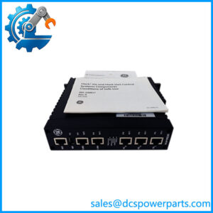
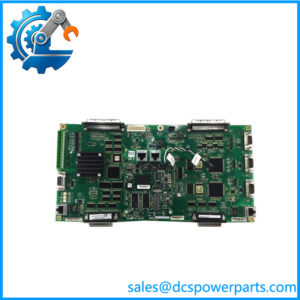
The GE IS200TREGH1BEC is identified as a TREG emergency-trip terminal board in the Mark VI turbine protection architecture. Its documented function includes switching the emergency trip circuit and supplying the positive side of the 125 VDC circuit to up to three trip solenoids. The board contains 12 relays, including nine trip relays arranged in three groups and three economizer relays.
Product Introduction
What the IS200TREGH1BEC Does
The GE IS200TREGH1BEC is a turbine emergency-trip terminal board used in GE Mark VI Speedtronic turbine protection systems. It interfaces the protection electronics with the physical trip circuit, controlling trip-solenoid power through relay logic. The TREG works with the associated VPRO protection module and complementary TRPG circuitry to provide the hardwired emergency-trip path.
This is safety-critical hardware. It is not a normal analog or digital I/O board. The TREG handles the physical interface between turbine protection logic and emergency trip devices, so exact terminal wiring, relay configuration, polarity, and board revision matter during replacement.
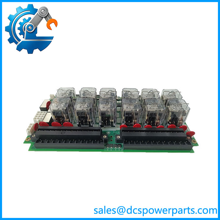
IS200TREGH1BEC
Application Scenarios & Field Pitfalls
Engineering Pain Point
A turbine can have healthy control CPUs, I/O processors, and monitoring software yet still fail an emergency-trip test because the physical trip circuit is compromised. With the IS200TREGH1BEC, troubleshooting has to follow the complete protection path: VPRO output, 28 VDC relay supply, TREG relay operation, 125 VDC feeder, TRPG return path, field wiring, and trip-solenoid condition. Replacing the TREG without checking those points can waste valuable outage time.
Typical Applications
- Gas Turbines — Emergency shutdown of fuel or steam admission systems through trip solenoids.
- Steam Turbines — Hardwired turbine protection and emergency trip circuits.
- Power Generation — Redundant turbine protection architectures using VPRO/TREG/TRPG hardware.
- Turbine Overhaul Projects — Replacement of degraded relay, terminal, or protection-interface hardware.
Technical Pitfalls to Avoid
- Do not confuse TREG with the main turbine controller.
The TREG is part of the emergency protection interface. It does not replace the main turbine control processor or general-purpose I/O system. - Check the complete 125 VDC trip path.
The TREG provides the positive side of the trip-solenoid circuit, while the complementary TRPG board provides the other side in the documented architecture. A TREG replacement alone cannot correct an open feeder, blown fuse, defective solenoid, or TRPG-side fault. - Verify the 28 VDC relay supply.
The TREG relay coils receive 28 VDC from the associated protection electronics. If the relays do not actuate, verify this supply before condemning the board. - Photograph every field connection before removal.
TREG wiring is safety-critical. Incorrect reconnection can create either a nuisance trip or, more seriously, a failure of the intended trip function. Record TB1/TB2 wiring, connector positions, and jumper configuration. - Confirm the exact hardware revision.
The BEC suffix represents a particular hardware revision/configuration. Available technical references indicate multiple TREG revisions, and not every revision should be assumed interchangeable without checking the Mark VI hardware documentation.
Related Products
- GE IS200TRPGH1B — Complementary turbine protection terminal hardware associated with the TREG architecture. The TRPG provides the complementary side of the trip circuit, so both boards must be evaluated together when troubleshooting an emergency-trip path.
- GE VPRO — Mark VI turbine protection module that provides the control-side logic and relay excitation associated with the TREG. The TREG cannot be evaluated independently of the protection controller.
- GE PPRO — Protection-controller architecture associated with later Mark VIe implementations. Do not assume a Mark VI TREG configuration automatically transfers to every Mark VIe installation. Verify the complete system architecture first.
- GE IS200TREG1B — Related TREG functional hardware within the Mark VI emergency-trip architecture. It is important when identifying the associated control/termination assembly, but it should not be treated as automatically equivalent to the IS200TREGH1BEC terminal board.
- GE IS200TSVOH1B — Related servo-valve termination hardware used in turbine control applications. It serves servo-interface functions rather than the emergency-trip relay path, making it complementary rather than a replacement.
- GE IS200TCTTG1A — Related Mark VI termination hardware used in turbine control signal interfacing. Its function is different from the TREG’s emergency-trip role and should not be selected as a functional substitute.
- GE IS200TRLYH1B — Related Mark VI relay-interface hardware. It may appear similar at the board level, but relay function and system position must be confirmed before substitution.
- GE IS200TVBAH2A — Related Mark VI VME/terminal interface hardware. It belongs to the broader turbine-control architecture but does not provide the TREG emergency-trip function.
Procurement note: Specify the complete number when sourcing a replacement. For this board, the functional description alone is not enough. Confirm the exact Mark VI architecture, board revision, VPRO/TRPG relationship, terminal wiring, jumper settings, and 125 VDC trip-circuit configuration before installation. This is protection hardware, so interchangeability should be established from the system documentation rather than inferred from connector or board appearance.